
- Call : +91 22 67436442
- exports@petrometflange.com
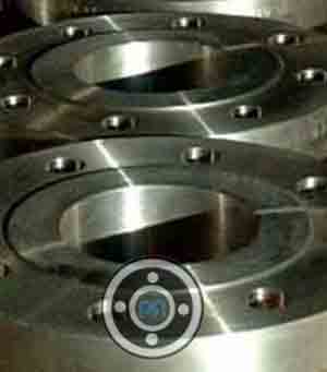
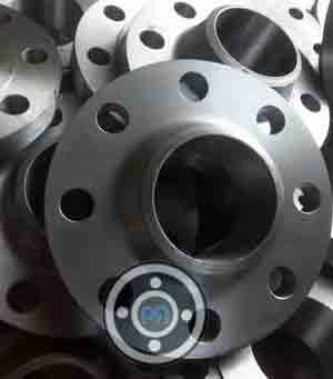
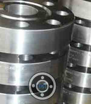
ASTM A182 F22 Flanges
- Home /
- ASTM A182 F22 Flanges
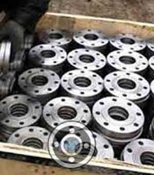
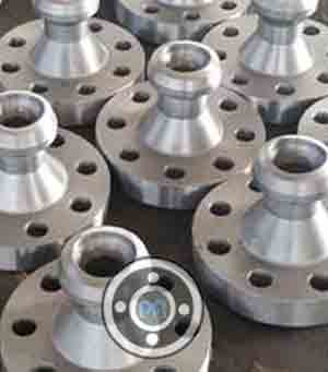
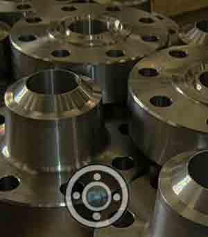
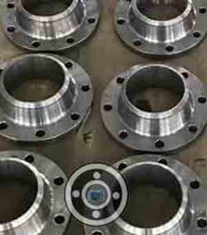
A182 F22 CL3 Blind Flange and SA 182 Gr F22 Weld Neck Flange manufacturer in India
What is ASTM A182 F22 Flanges?
The ASTM A182 is a specification of low alloy steel that contains a minimum amount of 2.25% chromium in its composition and it is of the grade F22. The ASTM A182 F22 Flanges are used in environments with crevice corrosion and stress corrosion cracking, as the material is resistant to them. It is also known for being resistive to various adverse conditions.
The ASTM A182 F22 Flanges are basically hardened by heat treatment and offer good erosion resisting properties. Due to its unique characteristics, the material is widely used for making things like cutlery, surgical instruments, turbines, and torques. As mentioned earlier, the ASTM A182 F22 Flanges show good resistance to erosion especially in acidic environments. Like any other flanges, these are available in different types such as plate flange, weld neck flange, lap joint flange, etc., and each of them have varied applications according to their structures. These are also available in different pressure classes that range between 150 to 2500.
The ASTM A182 F22 Flanges are mostly used for applications that are subjected to high temperatures. The flanges are high in strength and they offer excellent creep resistance in high temperature, along with features such as fatigue life, phase stability and resistance to oxidation and corrosion. Due to the economical material welding and high torque capacity, the F22 grade materials are ideal to be used with pumps. The ASTM A182 F22 Flanges are widely used in industries such as water supply systems, power plants, fabrication, food processing, and many more.
How to Order Chrome Moly Alloy A182 F22 Flanges
Clients can order Chrome Moly Alloy A182 F22 Flanges from some of the leading manufacturers. It is essential to ensure that high-quality raw materials are used, and proper standards are followed in the manufacturing process of the flanges. This would ensure that the end product is of the finest quality, and they would last really long. Before ordering, it is essential to know the dimensions of the products that clients would need. This would make the whole process easier. Preciseness and dimensional accuracy is very important when it comes to using flanges for any industry.
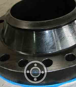
SA 182 F22 Lap Joint Flange Vs A182 Gr F22 RTJ Flange
A SA 182 F22 Lap Joint Flange can be described as a two component assembly that comes with a stub end and a lap joint ring that is placed over it. They are mostly used in piping systems that need frequent dismantling for inspections and maintenance. They are also used in large or har-to-adjust piping configurations due to the presence of its quick bolt hole alignment.
The A182 Gr F22 RTJ Flange is a machined metallic ring that has deep grooves and cuts in its face. These grooves help the metal rings to rest when the flange’s connecting bolts get tightened. The procedure helps in making the connection leak proof by ensuring a closely fitted seal. These flanges are mostly used in high pressure class (greater than 600) and high temperature services (427 degrees C).
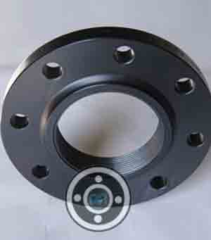
A182 F22 Class 3 Slip on Flange Vs SA182 gr F22 Weld neck Flanges
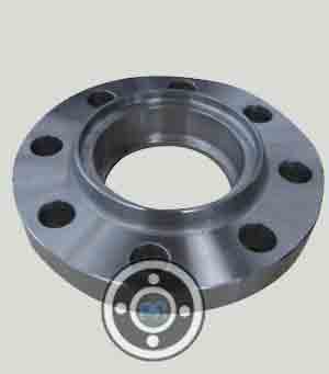
The difference between the A182 F22 Class 3 Slip on Flange and the SA182 gr F22 Weld neck Flanges can firstly be determined by their appearance. The slip-on flange is connected to the pipe with the help of two welds, present at the back and the inside of the flange, whereas the weld neck flange comes with a hub which tapers gradually from the bolted connection to the piping system.
Radiographic inspection is not allowed on the weld of slip-on flanges, whereas for the weld neck flange, the case is just the opposite. Also, there is a difference in their nominal pressure. The nominal pressure of the slip-on flange is between the range 0.6-4 MPa, while for weld neck flange, the range is between 1-25 MPa.
Also, the stiffness and the strength of slip-on flanges are higher and they offer better leak-proof connections compared to the weld neck flanges. The slip-on flanges also come with larger diameters, and hence they have lesser weight and cost compared to the weld neck flanges.

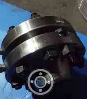
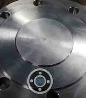
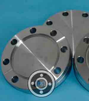
ASTM A182 F22 Flanges
Manufacturer of A 182 F22 Steel Socket Weld Flange and SA 182 F22 CL3 Slip On Flange since 2014 according to ASME B16.5
SA182 F22 Cl3 Flange Vs A182 F22 Class 1 Flange
The A182 F22 Class 1 Flanges are the most commonly used flange, even with lower mechanical properties compared to the SA182 F22 Cl3 Flange. In fact, the class 3 flange is very rare and also the strongest flange in the given specifications. Both the flanges cover forged low alloy and stainless steel piping and they are primarily used for high pressure applications.
Table of Content
- Standard Specification of ASTM A182 F22 Flange
- ASTM A182 F22 Class 1 Slip on Flange Dimensions
- SA182 F22 Cl3 Blind Flange Dimensions
- Alloy Steel F22 Weld Neck Flange Dimensions
- Price List of ASTM A182 F22 Flange
- Pressure Rating of ASTM A182 F22 Class 2 Flanges
- A182 Grade F22 Flanges Weight Chart
- A182 F22 Chemical Composition
- ASTM A182 F22 Mechanical Properties
Standard Specification of ASTM A182 F22 Flange
| Size Range | 1/2″ to 48″ |
|---|---|
| Chart of Pressure Rating | 300 LBS, 2500 LBS, 1500 LBS, 900 LBS, 150 LBS, 600 LBS |
| JIS | 40 K, 16 K, 5K, 10 K, 30 K, 20 K, 63 K |
| DIN Pressure Calculation | 25Bar 40Bar 16Bar 6Bar 10Bar / PN64 PN10 PN25 PN16 PN6 PN40 |
| Manufacturer of Connect / Flange Face Type | LJF, RF, RTJ, FF, Small Tongue, Large Tongue & Groove |
| Test | Magnetic particle detector, X-ray detector, Ultrasonic flaw detector, Direct-reading Spectrograph, Hydrostatic testing machine |
| Origin | Japan / West Europe / Indian / USA / Korean |
| Manufacturer of | GOST, JIS, ANSI, DIN, UNI, BS, AWWA, AS2129, SABS, NFE, EN etc. |
| UNI / EN | 16Bar 6Bar 40Bar 10Bar 25Bar |
| Standards Provided By Manufacturer | ISO70051, MSS S44, BS1560-3.1, API7S-43, B16.48, ANSI/ASME B16.5, B16.47 Series A & B, BS4504, JISB2220, ASME/ANSI B16.5/16.36/16.47A/16.47B, API605, BS 10, EN-1092, DIN, API7S-15, EN1092 |
| Common Types By Manufacturer | Threaded / Screwed / Forged / Plate |
| Equipment | Pushing Machine, Press machine, Sand-blasting machine, Bending machine, electric bevelling machine etc |
| Production technique Used By Manufacturer | Heat treated, Forged and machined |
| Coating | Zinc Plated, Anti-rust Paint, Yellow Transparent, Oil Black Paint, Cold and Hot Dip Galvanized |
Well known SA182 F22 Cl3 Blind Flange wholesalers, distributor, supplier, exporters, importer, stockists, dealers, stockholders and Manufacturer in Mumbai.
ASTM A182 F22 Class 1 Slip on Flange Dimensions

| Size in Inch | Size in mm | No of Bolts | Outer Dia. | Hub OD | ISO Stud Size | Flange Length | RF Height | Flange Thick. | RF Dia. | PCD | Hole Size | Socket Bore | Weight in kg |
| A | C | D | F | B | E | G | H | ||||||
| 1/2 | 15 | 4 | 90 | 30 | M14 | 14 | 2 | 9.6 | 34.9 | 60.3 | 5/8 | 22.2 | 0.8 |
| 1 | 25 | 4 | 110 | 49 | M14 | 16 | 2 | 12.7 | 50.8 | 79.4 | 5/8 | 34.5 | 0.9 |
| 3/4 | 20 | 4 | 100 | 38 | M14 | 14 | 2 | 11.2 | 42.9 | 69.9 | 5/8 | 27.7 | 0.9 |
| 1 1/4 | 32 | 4 | 115 | 59 | M14 | 19 | 2 | 14.3 | 63.5 | 88.9 | 5/8 | 43.2 | 1.4 |
| 2 | 50 | 4 | 150 | 78 | M16 | 24 | 2 | 17.5 | 92.1 | 120.7 | 3/4 | 61.9 | 2.3 |
| 1 1/2 | 40 | 4 | 125 | 65 | M14 | 21 | 2 | 15.9 | 73 | 98.4 | 5/8 | 49.5 | 1.4 |
| 2 1/2 | 65 | 4 | 180 | 90 | M16 | 27 | 2 | 20.7 | 104.8 | 139.7 | 3/4 | 74.6 | 3.2 |
| 3 | 80 | 4 | 190 | 108 | M16 | 29 | 2 | 22.3 | 127 | 152.4 | 3/4 | 90.7 | 3.7 |
| 4 | 100 | 8 | 230 | 135 | M16 | 32 | 2 | 22.3 | 157.2 | 190.5 | 3/4 | 116.1 | 5.9 |
| 3 1/2 | 90 | 8 | 215 | 122 | M16 | 30 | 2 | 22.3 | 139.7 | 177.8 | 3/4 | 103.4 | 5 |
| 5 | 125 | 8 | 255 | 164 | M20 | 35 | 2 | 22.3 | 185.7 | 215.9 | 7/8 | 143.8 | 6.8 |
| 8 | 200 | 8 | 345 | 246 | M20 | 43 | 2 | 27 | 269.9 | 298.5 | 7/8 | 221.5 | 13.7 |
| 10 | 250 | 12 | 405 | 305 | M24 | 48 | 2 | 28.6 | 323.8 | 362 | 1 | 276.2 | 19.5 |
| 6 | 150 | 8 | 280 | 192 | M20 | 38 | 2 | 23.9 | 215.9 | 241.3 | 7/8 | 170.7 | 8.6 |
| 12 | 300 | 12 | 485 | 365 | M24 | 54 | 2 | 30.2 | 381 | 431.8 | 1 | 327 | 29 |
| 24 | 600 | 20 | 815 | 663 | M33 | 81 | 2 | 46.1 | 692.2 | 749.3 | 1 3/8 | 616 | 100 |
| 16 | 400 | 16 | 595 | 457 | M27 | 62 | 2 | 35 | 469.9 | 539.8 | 1 1/8 | 410.5 | 54 |
| 18 | 450 | 16 | 635 | 505 | M30 | 67 | 2 | 38.1 | 533.4 | 577.9 | 1 1/4 | 461.8 | 59 |
| 14 | 350 | 12 | 535 | 400 | M27 | 56 | 2 | 33.4 | 412.8 | 476.3 | 1 1/8 | 359.2 | 41 |
| 20 | 500 | 20 | 700 | 559 | M30 | 71 | 2 | 41.3 | 584.2 | 635 | 1 1/4 | 513.1 | 75 |
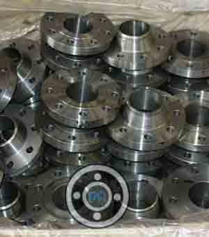
Supplier of ASTM A182 F22 Class 3 Spectacle Blind Flange and SA-182-F22 Lap Joint Flange for Oil, Gas and Chemical Process Plants
SA182 F22 Cl3 Blind Flange Dimensions

| Size in Inch | Size in mm | ISO Stud Size | RF Height | Outer Dia. | RF Dia. | Hole Size | PCD | No of Bolts | Bolt Size UNC | Flange Thickness | RF Stud Length | Weight in kg |
| D | A | C | E | B | ||||||||
| 1/2 | 15 | M20 | 7 | 135 | 34.9 | 7/8 | 88.9 | 4 | 3/4 | 30.2 | 120 | 3.2 |
| 3/4 | 20 | M20 | 7 | 140 | 42.9 | 7/8 | 95.2 | 4 | 3/4 | 31.8 | 125 | 3.7 |
| 1 | 25 | M24 | 7 | 160 | 50.8 | 1 | 108 | 4 | 7/8 | 35 | 140 | 5 |
| 1 1/4 | 32 | M27 | 7 | 185 | 63.5 | 1 1/8 | 130.2 | 4 | 1 | 38.1 | 150 | 7.8 |
| 1 1/2 | 40 | M30 | 7 | 205 | 73 | 1 1/4 | 146 | 4 | 1 1/8 | 44.5 | 170 | 10.5 |
| 2 | 50 | M27 | 7 | 235 | 92.1 | 1 1/8 | 171.4 | 8 | 1 | 50.9 | 180 | 18 |
| 2 1/2 | 65 | M30 | 7 | 265 | 104.8 | 1 1/4 | 196.8 | 8 | 1 1/8 | 57.2 | 195 | 25.5 |
| 3 | 80 | M33 | 7 | 305 | 127 | 1 3/8 | 228.6 | 8 | 1 1/4 | 66.7 | 220 | 39 |
| 4 | 100 | M39 | 7 | 355 | 157.2 | 1 5/8 | 273 | 8 | 1 1/2 | 76.2 | 255 | 61.5 |
| 5 | 125 | M45 | 7 | 420 | 185.7 | 1 7/8 | 323.8 | 8 | 1 3/4 | 92.1 | 300 | 102 |
| 6 | 150 | M52 | 7 | 485 | 215.9 | 2 1/8 | 368.3 | 8 | 2 | 108 | 345 | 157 |
| 8 | 200 | M52 | 7 | 550 | 269.9 | 2 1/8 | 438.2 | 12 | 2 | 127 | 380 | 241 |
| 10 | 250 | M64 | 7 | 675 | 323.8 | 2 5/8 | 539.8 | 12 | 2 1/2 | 165.1 | 490 | 470 |
| 12 | 300 | M72 | 7 | 760 | 381 | 2 7/8 | 619.1 | 12 | 2 3/4 | 184.2 | 540 | 575 |
Alloy Steel F22 Weld Neck Flange Dimensions

| Flange NPS | H | Inside Diameter |
Flat Face Thickness (T2) |
Outside Diameter |
Raised Face (RF) |
Raised Face (R) |
H1 | Raised Face Thickness (T) |
T1 | Bolt Circle (BC) |
Bolt Hole (B) |
No. of Bolt Holes |
|---|---|---|---|---|---|---|---|---|---|---|---|---|
| 1/2" | 1.19" | 0.62" | 1.82" | 3.50" | .063" | 1.38" | 0.84" | 1.88" | .38" | 2.38" | .62" | 4 |
| 1-1/4" | 2.31" | 1.38" | 2.19" | 4.62" | .063" | 2.50" | 1.66" | 2.25" | .56" | 3.50" | .62" | 4 |
| 3/4" | 1.50" | 0.82" | 2.00" | 3.88" | .063" | 1.69" | 1.05" | 2.06" | .44" | 2.75" | .62" | 4 |
| 1-1/2" | 2.56" | 1.61" | 2.38" | 5.00" | .063" | 2.88" | 1.90" | 2.44" | .62" | 3.88" | .62" | 4 |
| 1" | 1.94" | 1.05" | 2.13" | 4.25" | .063" | 2.00" | 1.32" | 2.19" | .50" | 3.12" | .62" | 4 |
| 2" | 3.06" | 2.07" | 2.44" | 6.00" | .063" | 3.62" | 2.38" | 2.50" | .69" | 4.75" | .75" | 4 |
| 2-1/2" | 3.56" | 2.47" | 2.69" | 7.00" | .063" | 4.12" | 2.88" | 2.75" | .82" | 5.50" | .75" | 4 |
| 3" | 4.25" | 3.07" | 2.69" | 7.50" | .063" | 5.00" | 3.50" | 2.75" | .88" | 6.00" | .75" | 4 |
| 4" | 5.31" | 4.03" | 2.94" | 9.00" | .063" | 6.19" | 4.50" | 3.00" | .88" | 7.50" | .75" | 8 |
| 5" | 6.44" | 5.05" | 3.44" | 10.00" | .063" | 7.31" | 5.56" | 3.50" | .88" | 8.50" | .88" | 8 |
| 3-1/2" | 4.81" | 3.55" | 2.75" | 8.50" | .063" | 5.50" | 4.00" | 2.81" | .88" | 7.00" | .75" | 8 |
| 6" | 7.56" | 6.07" | 3.44" | 11.00" | .063" | 8.50" | 6.63" | 3.50" | .94" | 9.50" | .88" | 8 |
| 8" | 9.69" | 7.98" | 3.94" | 13.50" | .063" | 10.62" | 8.63" | 4.00" | 1.06" | 11.75" | .88" | 8 |
| 22" | 24.25" | 21.25" | 5.82" | 29.50" | .063" | 25.25" | 22.00" | 5.88" | 1.75" | 27.25" | 1.38" | 20 |
| 10" | 12.00" | 10.02" | 3.94" | 16.00" | .063" | 12.75" | 10.75" | 4.00" | 1.13" | 14.25" | 1.00" | 12 |
| 12" | 14.38" | 12.00" | 4.44" | 19.00" | .063" | 15.00" | 12.75" | 4.50" | 1.19" | 17.00" | 1.00" | 12 |
| 16" | 18.00" | 15.25" | 4.94" | 23.50" | .063" | 18.50" | 16.00" | 5.00" | 1.38" | 21.25" | 1.12" | 16 |
| 18" | 19.88" | 17.25" | 5.44" | 25.00" | .063" | 21.00" | 18.00" | 5.50" | 1.50" | 22.75" | 1.25" | 16 |
| 14" | 15.75" | 13.25" | 4.94" | 21.00" | .063" | 16.25" | 14.00" | 5.00" | 1.32" | 18.75" | 1.12" | 12 |
| 20" | 22.00" | 19.25" | 5.63" | 27.50" | .063" | 23.00" | 20.00" | 5.69" | 1.63" | 25.00" | 1.25" | 20 |
| 24" | 26.12" | 23.25" | 5.94" | 32.00" | .063" | 27.25" | 24.00" | 6.00" | 1.82" | 29.50" | 1.38" | 20 |
Price List of ASTM A182 F22 Flange
| ASTM A182 F22 Flange Price Per Piece in India | F22 Alloy Steel Pipe Flanges Price in INR | SA182 F22 Cl3 Flanges Price in UAE Dirham | ASTM A182 Gr F22 Cl3 Flange Price in USD |
| FLANGE,SOCKETWELD 1-900,1500 RTJ SCH 160,CMTR ASTM A182M F22 CLASS 3 Per Unit | 4,300 | UAE Dirham 208.16 | $56.67 |
| FLANGE,WELD NECK 3-300 RF SCH 40 SA182 F22 CLASS 3 Per Kg | 4,500 | UAE Dirham 59.32 | $217.84 |
Are you looking for a ASTM A182 F22 Flange manufacturer in India? Bulk ASTM A182 Gr F22 Flanges for Piping Connection at the Lowest Price. Compare the prices of ASTM A182 F22 Class 2 Flanges with those of other manufacturers.
Pressure Rating of ASTM A182 F22 Class 2 Flanges
| Temperature °F | Class 150 | Class 600 | Class 1500 | Class 400 | Class 900 | Class 300 | Class 2500 |
| -20 to 100 | 275 | 1440 | 3600 | 960 | 2160 | 720 | 6000 |
| 300 | 205 | 1080 | 2700 | 720 | 1620 | 540 | 4500 |
| 200 | 230 | 1200 | 3000 | 800 | 1800 | 600 | 5000 |
| 400 | 190 | 995 | 2485 | 660 | 1490 | 495 | 4140 |
| 600 | 140 | 875 | 2185 | 580 | 1310 | 435 | 3640 |
| 650 | 125 | 860 | 2150 | 575 | 1290 | 430 | 3580 |
| 500 | 170 | 930 | 2330 | 620 | 1395 | 465 | 3880 |
| 700 | 110 | 850 | 2125 | 565 | 1275 | 425 | 3540 |
| 750 | 95 | 830 | 2075 | 555 | 1245 | 415 | 3460 |
| 850 | 65 | 790 | 1980 | 530 | 1190 | 395 | 3300 |
| 800 | 80 | 805 | 2015 | 540 | 1210 | 405 | 3360 |
| 900 | 50 | 780 | 1945 | 520 | 1165 | 390 | 3240 |
| 950 | 35 | 765 | 1910 | 510 | 1145 | 380 | 3180 |
| 1000 | 20 | 640 | 1605 | 430 | 965 | 320 | 2675 |
| 1100 | 20 | 515 | 1285 | 345 | 770 | 255 | 2145 |
| 1150 | 20 | 400 | 995 | 265 | 595 | 200 | 1655 |
| 1050 | 20 | 615 | 1545 | 410 | 925 | 310 | 2570 |
| 1200 | 20 | 310 | 770 | 205 | 465 | 155 | 1285 |
| 1250 | 20 | 225 | 565 | 150 | 340 | 115 | 945 |
| 1300 | 20 | 170 | 430 | 115 | 255 | 85 | 715 |
| 1400 | 20 | 95 | 240 | 65 | 145 | 50 | 400 |
| 1350 | 20 | 125 | 310 | 80 | 185 | 60 | 515 |
| 1450 | 15 | 70 | 170 | 45 | 105 | 35 | 285 |
| 1500 | 10 | 55 | 135 | 35 | 80 | 25 | 230 |
BS 10 Table E/ / EN 1092 Raised Face ASTM A182 F22 CL3 Orifice Flanges and F22 Alloy Steel Threaded Flange Material manufacturer in India
A182 Grade F22 Flanges Weight Chart
| NPS (Nominal Pipe Size) | NPT (Threaded) | WRNR (Weld Neck) | SWRF (Socket Weld) | Loose (Lap Joint) | SORF (Slip On) | BLRF (Blind) |
|---|---|---|---|---|---|---|
| ½ | 1 | 2 | 2 | 1 | 1 | 2 |
| ¾ | 2 | 2 | 2 | 2 | 2 | 2 |
| 1 | 2 | 3 | 2 | 2 | 2 | 2 |
| 1¼ | 3 | 3 | 3 | 3 | 3 | 3 |
| 1½ | 3 | 4 | 3 | 3 | 3 | 4 |
| 2 | 5 | 6 | 5 | 5 | 5 | 5 |
| 2½ | 8 | 10 | 8 | 8 | 8 | 7 |
| 3 | 9 | 11.5 | 9 | 9 | 9 | 9 |
| 3½ | 12 | 12 | 11 | 11 | 11 | 13 |
| 4 | 13 | 16.5 | 13 | 13 | 13 | 17 |
| 5 | 15 | 21 | 15 | 15 | 15 | 20 |
| 6 | 19 | 26 | 19 | 19 | 19 | 27 |
| 8 | 30 | 42 | 30 | 30 | 30 | 47 |
| 10 | 43 | 54 | 43 | 43 | 43 | 70 |
| 12 | 64 | 88 | 64 | 64 | 64 | 123 |
| 14 | 90 | 114 | 90 | 105 | 90 | 140 |
| 16 | 98 | 140 | 98 | 140 | 106 | 180 |
| 18 | 130 | 165 | 130 | 160 | 130 | 220 |
| 20 | 165 | 197 | 165 | 195 | 165 | 285 |
| 22 | 185 | 225 | 185 | 245 | 185 | 355 |
| 24 | 220 | 268 | 220 | 275 | 220 | 430 |
A182 F22 Chemical Composition
| Grade | C | Mn | Si | S | P | Cr | Mo |
| A182 F22 | 0.05 – 0.15 | 0.3 – 0.6 | 0.5 | 0.03 | 0.045 | 0.8 – 1.25 | 0.044 – 0.65 |
ASTM A182 F22 Mechanical Properties
| Grade | Tensile Strength (Mpa) | Yield Strength (Mpa) | Elongation % |
| A182 F22 | 205 | 415 | 20 |
SA 182 F22 Equivalent
| STANDARD | UNS | WNR. |
| ASTM A182 F22 | K21590 | 1.7380 |
Check SA 182 F22 Plate/ Forged Flange and A182 Gr F22 Flat/ Puddle/ Long Weld Neck Flange pressure rating, dimensions & price list
Types of ASTM A182 F22 Flange
ASME SA182 F22 Class 3 SORF Flanges
5000 NB ASME SA182 F22 Orifice Flanges
A182 F22 WNRF Flange
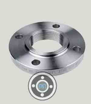
150 LBS A182 F22 Cl 3 Threaded Flange

SA-182 F22 Girth Flanges
A182 Grade F22 Lapped Joint Flange
600 LBS ASTM A182 F22 Alloy Steel Slip On Flange

SA182 F22 Tongue & Groove Flange
ASTM A182 Gr F22 Cl3 Long Weld Neck Flange
2500 LBS F22 ASTM A182 Blind Flange
ASTM A182 F22 Cl3 Nipoflange Flanges
Alloy Steel F22 Spectacle Blind Flange
900 LBS ASTM A182 F22 Class 1 Socket Weld Flange
ASTM A182 F22 Class 2 Screwed Flange
ASTM A182 Grade F22 Class 3 Expander Flanges
1500 LBS A182 Gr F22 Weld Neck Flanges
ASTM A182 Gr F22 BLRF Flanges
SA182 F22 Cl3 Blind Flange
300 LBS ASTM A182 F22 Reducing Flanges

ASTM A182 F22 Class 3 SWRF Flanges
15 NB SA182 F22 Cl3 Ring Joint Flange
ASTM A182 F22 Alloy Steel Flange Applications
- Ship Building
- Fossil Fuel Power Plants
- Power Plants
- Oil And Gas Industry
- Refineries
- Marine Applications
- Paper & Pulp
- Nuclear Power
SA182 F22 Yield Strength
| Yield Strength | 30 [205] |
A182 Gr F22 Cl3 Heat Treatment
| F22, Class 1, 3 | Anneal, or normalise and temper; Minimum austenitizing/solutioning temperature: 1600°F [900°C]; Cooling medium: furnace or air cool Tempering temperature: 1250°F [675°C]. |
ASTM A182 Grade F22 Young's Modulus
| Young's Modulus | 200 |
ASTM A182 F22 Density
| Density | 8.0 G/CM3 |
SA182 F22 Cl3 Welding
Most techniques can weld A182 F22 Flanges as long as proper safeguards are taken to minimize flaws. It is critical to understand the material's composition, which can be obtained through a mill sheet or a dedicated chemical study, because composition has a substantial impact on weldability.
Manufacturing Equipments For ASME SA182 F22 Class 3 Flanges
| Name and Description | Capacity |
| 2000T hydraulic press | Max. single forging in 9T |
| 800 hydraulic press | Max. single forging in 5T |
| Vertical lathe | From 1600 to 5000mm |
| 6T electrical hydraulic hammer | Max.single forging in 5T |
| 3600Thydraulic press | Max. single forging in 18T |
| 3T electrical hydraulic hammer | Max.single forging in3T |
| Air hammer | Max.single forging from250kg to 1000kg |
| Forging operation machine | Max.singe forging from20T-5T |
| CNC driling machine | Max.5000mm |
| Heat treatment Furance | Max.8000*5000*1500mm |
| Horizontal lathe | Max.5000mm |
| Band sawing machine | 260-1300mm |
Flanges Material
Pipe Fittings Material
Other Products