
- Call : +91 22 67436442
- exports@petrometflange.com
Stainless Steel Slip On Flange
- Home /
- Stainless Steel Slip On Flange
Looking for Class 150 Slip On Flange manufacturer in India? Petromet Flange produces SORF Flange in SS, Carbon Steel, Alloy, Inconel, Hastelloy, Copper, Titanium, Monel, Aluminium and Nickel
What Is Slip On Flanges?
The slip on flange is one of the most popular pipe flanges that comes with a bore in the center. The pipe is first passed through the bore, and then double welded on inner and outer sides so as to ensure a more secured connection. Unlike the weld neck flange, they do not come with a neck which would rest on the pipe. Thus, double welding is a necessary step. It is primarily used for low pressure applications. It can be described as a simple yet an excellent alternative to the weld neck flange. This is because it does not come with a weld bevel.
The slip on flanges are affordable and can be installed very easily. They can also be sometimes used as lap joint flanges, if the Type B or C ends are handled. They have a wide range of low pressure models and their diameters can be customized according to the pipe. The slip on flanges can be mounted in small spaces and they are very easy to align. They are mostly used for low pressure service where the risk of leakage is very less.
When To Use Carbon Steel Slip On Flanges?
After carrying out the quenching procedure on the Carbon Steel Slip On Flanges, which helps in strengthening and hardening the steel, they can be used in a wide range of industries. This would include engineering, construction, and petrochemicals.
Do Stainless Steel Slip On Flanges Have Schedules?
The Stainless Steel Slip On Flanges do not have a schedule as for this flange, the inner diameter is basically determined by measuring the pipe’s outer diameter.
How Do SORF Flanges Work?
The SORF flanges are basically used in fabricated applications. They are attached to the pipe with the help of fillet weld which is done at the hub. It is also done at the end of the pipe on the inner side of the flanges.
Slip On Raised Face Flange Vs Slip On Flat Face Flange
The main difference between the Slip On Raised Face Flange and the Slip On Flat Face Flange is in their structure. For SORF, the gasket is located above the bolting surface whereas for SOFF, the gasket surface and the bolting circle face are on the same plane. SORF is capable of giving more secured connections compared to SOFF.

Stainless Steel Slip On Flange
Manufacturer of Carbon Steel Slip On Flange in ASTM A105, A350 LF2, A694 Gr F42 - F70 and A516 Gr.70
Table of Content
- Stainless Steel Slip On Flange Specification
- Available Slip On Flat Face Flange Material Grade
- Slip On Flange Types
- Slip On Flange Price List
- Class 125 Slip On Flange Dimensions
- ANSI 150 Slip On Flange Dimensions
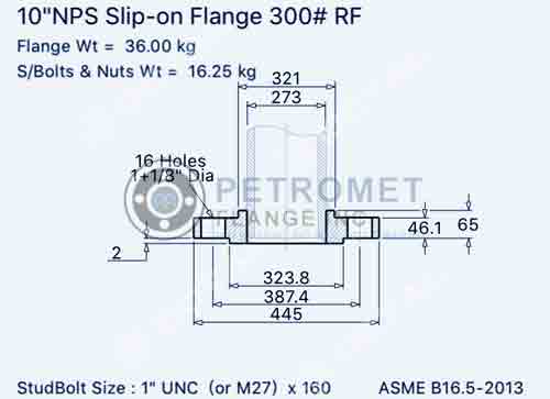
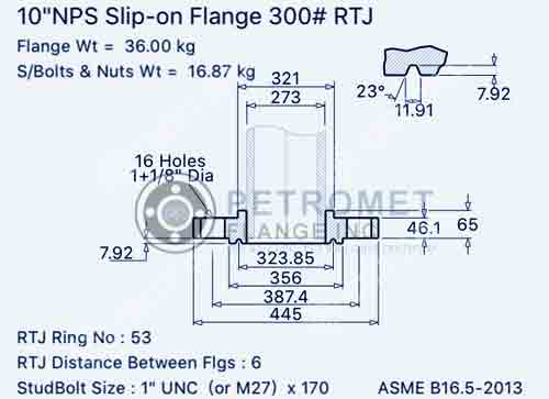
- 300 Lb Slip On Flange Dimensions
- Class 600 Slip On Flange Dimensions
- Class 900 Slip On Flange Dimensions
- Class 1500 Slip On Flange Dimensions
- Class 2500 Slip On Flange Dimensions
- Pn16 Slip On Flange Weights
- Slip On Reducing Flange Weight Chart
- PN10 Slip On Flange Dimensions
- MS Slipon Flange Weight Chart
- Stainless Steel Slip On Flange Weight
- Slip On Flange Gasket
- Slip On Flange Pressure and Temperature Ratings
- Features of Stainless Steel Slip On Flange
- Applications of Carbon Steel Slip On Flange
- Facing Types of Slip On Pipe Flange
- How To Weld Slip On Flange
Stainless Steel Slip On Flange Specification
| Dimensions | ASME B16.5, ASME B16.47 Series A & B, MSS SP44 |
| Size | 1/2" to 48" |
| Class | 300 LBS, 150 LBS, 900 LBS, 600 LBS, 1500 LBS, 2500 LBS |
| JIS | 5K, 16 K 10 K, 20 K, 40 K, 30 K, 63 K |
|---|---|
| UNI | 6Bar 16Bar 10Bar 25Bar 40Bar |
| Coating/Surface Treatment By Manufacturer | Antirust Paint, Oil Black Paint, Yellow Transparent, Zinc Plated, Cold and Hot Dip Galvanized |
| EN | 6Bar 25Bar 10Bar 40Bar 16Bar |
| BS | BS4504 , BS4504, BS1560, BS10 |
| Flange Face Type Provided By Manufacturer | RF (Raised Face), RTJ (Ring Type Joint) |
| Value Added Services | CNC Machining, Customised Flanges |
| Making Methods Provided By Manufacturer | Casting And Forging Rolling And Cutting |
| Flanges Test | Hydrostatic testing machine/ UI trasonic flaw detector/ X-ray detector/ Direct-reading Spectrograph/ Magnetic particle detector |
| Flanges Equipment | Pushing Machine/ electric bevelling machine/ Press machine/ Bending machine/ Sand-blasting machine etc |
| Outer diameters | 1/2” to 24” |
| Standards Provided By Manufacturer | EN-1092, DIN, API7S-43, API605, B16.48, ISO70051, MSS S44, ANSI/ASME B16.5, B16.47 Series A & B, BS4504, BS 10, API7S-15, JISB2220, BS1560-3.1, ASME/ANSI B16.5/16.36/16.47A/16.47B, EN1092 |
Well known Slip on Flanges importer, stockists, supplier, dealers, exporters, wholesalers, distributor, stockholders and Manufacturer in Mumbai.
Available Slip On Flat Face Flange Material Grade
| Stainless Steel | ASTM A182 Gr. 304, 304L, 309, 316, 310, 316L, 317L, 321, 347, 904L |
| Duplex Steel | ASTM A 182, ASME SA 182 UNS NO S31803, S32205. Werkstoff No. 1.4462 |
| Carbon Steel | High Yield CS ASTM A694 / A694 (F52 F56 F60 F65 F70 F80), A181 LF2, A105N, ASTM A350 LF2 / ASME SA350, ASTM/ASME A/SA105 A/SA105N & ASTM A105 / ASME SA105, P235GH, P245GH, P250GH, RST37.2, C22.8, S235JR, ST37, A516 Gr.70 A36, A694 F42, F46, F52, F60, F65, F706 |
| Copper Nickel | Cupro Nickel 70/30 (C71500), Copper Nickel 90/10 (C70600 ), ASTM / ASME SB 62 / 151 / 61 / 152, UNS C71640 |
| Nickel Alloy | ASTM / ASME SB 564 UNS 4400 (MONEL 400 ), UNS 2200 ( NICKEL 200 ), UNS 8825 INCONEL (825), UNS 2201 (NICKEL 201 ), UNS 8020 ( ALLOY 20 / 20 CB 3, UNS 6601 ( INCONEL 601 ), UNS 6625 (INCONEL 625), UNS 6600 (INCONEL 600 ), UNS 10276 ( HASTELLOY C 276 ) |
| Alloy Steel | F11, F12, F5, F9, F22, F91 |
| Other | Titanium, Aluminium, 254 SMO |
What is a slip-on flange?
Slip-on look like a ring that is placed on the pipe end. The flange face extends from the end of the pipe having enough distance so that weld beads can be applied to its inner diameter. It has a lesser material cost and can be aligned easily. With Type B or Type C stub ends, SORF can also be used as a lap joint. Its us available in different forms, like raised faces and flat faces. This is a useful choice for low-pressure applications, and hence slip-on material are widely used in various fluid pipelines.
Raised face vs reducing
Raised face or SORF are the most common, and they can easily be identified through their appearances. Here, the surface of the gasket is raised over the face of the bolting circle. Flat face flanges have the gasket surface as the face of the bolting surface. It does not have a ridge-like elevated face and allows full contact between the gasket and the mating surface.
The slip-on flanges are slipped onto the end of a pipe, and then it is welded. The welding is done around the contact points, both inside and outside the pipe and the forging. Weld-neck or buttweld connections are stronger than sorf.
Advantages and disadvantages of SORF
The advantages are as follows:
- It is a low installation cost.
- The accuracy of the cut pipe can be ensured within less time.
- These are quite easy to align.
- It has a low hub as the flanges are slipped into the pipe before welding.
- For slip-on, the welding is done on both the inner and outer sides to ensure greater strength.
One of the main design disadvantages of this connection is that it cannot guarantee no leakage. Even though it is mostly used in low-pressure applications, there are some chances of leakage. Therefore, it cannot be used for high-pressure fluids or hazardous gases.
These forgngs are mostly used for liquids at low pressure or for those who have the least chances for leakage. These fixings are mostly used in cooling water lines, firefighting water lines, low-pressure airlines, etc.
SORF stands for slip-on raised face. When these connection are attached to the pipe by fillet welding at the hub (collar) and the end of the pipe inside the flange, these are also available without the hub. Petromet is one of the top manufacturers of Sorf with hub and without hub.
Slip On Flange Types

SS 304 Slip On Flange

316 SS Slip On Flange

A105 Slip On Flange

Stainless Steel Slip On Flange

Carbon Steel Slip on Flange

Alloy Steel Rf Slip On Flange

Duplex Raised Face Slip On Flange

Super Duplex Flat Face Slip On Flange

Titanium SORF Flange

Mild Steel Reducing Slip On Flange

Nickel Alloy Slip On Integral Flange

Copper Slip On Pipe Flange

Inconel Slip On Reducing Flange

Hastelloy Slip On Flange

Ductile Iron Slip On Raised Face Flange

Gi Slip On Flat Face Flange

Aluminum Hubbed Slip On Flange

Alloy Steel Slip On Joint Flange

ASTM A105 Slip On Boss Flange

ASTM A516 Gr.70 Slip On Backing Flange

ASTM A182 F316 Slip On Composite Flange

ASTM A182 F304 Slip on Exhaust Flange

ASTM A350 LF2 PN6 Slip on Flange

Class 150 UNS S31803 SORF Flange

Class 300 A182 F11 Threaded Slip On Flange

Class 600 Stainless Steel 304 SORF Flange

Class 900 316 Stainless Steel Slip on Flange
European Directive 2014/68/eu certified Slip On Flange manufacturer in India offers large selection of ASTM A105 SORF Flange and ASTM A350 LF2 Slip On Reducing Flange in Mumbai
Slip On Flange Price List
| Slip on Flanges Price Per Piece in India | Price Applicable for jan 2022 to june 2022 | Price Applicable for July 2022 to December 2022 |
| SIZE=0.500 SLIP ON FLANGES 150 A105N RF | US $8.94 | US $10.94 |
| FLANGES, SLIP-ON 6 IN RAISED FACE ANSI 150 LB 8-HOLE CARBON STEEL BLASTED AND COATED Per Piece | US $72.70 | US $74.70 |
| A182 GR.F304/304L ANSI B16.5 FLANGES.SLIP ON RAISED FACE,300#DN25 Per Kg | US $4.30 | US $6.30 |
| SLIP ON FLANGES RAISED FACE ANSI B16.5 S.S304 SIZE:2MMX150# Per Piece | US $8.00 | US $10.00 |
| FLANGE SOLID SLIP ON FF- 90/10 CU/NI UNS NO-C70600 Per Piece | US $27.16 | US $29.16 |
This is an approximate Cost of Pn16 Slip On Flange in India. Feel free to contact us latest price list of Carbon Steel Slip On Flanges in Mumbai. Compare our price with other Slip On Flanges Manufacturer In India.
Class 125 Slip On Flange Dimensions
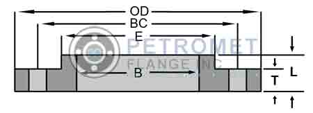
| Nominal Size |
Outside Diameter (OD) |
Thickness (T) |
Diameter at Base (E) |
Bore (B) |
LTH (L) |
Drilling - Bolt Circle (BC) |
Drilling - Hole Diameter | Drilling - No. of Holes |
Weight (lbs) |
|---|---|---|---|---|---|---|---|---|---|
| 26 | 34.25 | 2 | 28.5 | 26.19 | 3.375 | 31.75 | 1.375 | 24 | 235 |
| 28 | 36.5 | 2.062 | 30.75 | 28.19 | 3.438 | 34 | 1.375 | 28 | 269 |
| 30 | 38.75 | 2.125 | 32.75 | 30.19 | 3.5 | 36 | 1.375 | 28 | 303 |
| 32 | 41.75 | 2.25 | 35 | 32.19 | 3.625 | 38.5 | 1.625 | 28 | 375 |
| 34 | 43.75 | 2.312 | 37 | 34.19 | 3.688 | 40.5 | 1.625 | 32 | 401 |
| 36 | 46 | 2.375 | 39.25 | 36.19 | 3.75 | 42.75 | 1.625 | 32 | 452 |
| 38 | 48.75 | 2.375 | 41.75 | 38.19 | 3.75 | 45.25 | 1.625 | 32 | 528 |
| 40 | 50.75 | 2.5 | 43.75 | 40.19 | 3.875 | 47.25 | 1.625 | 36 | 573 |
| 42 | 53 | 2.625 | 46 | 42.19 | 4 | 49.5 | 1.625 | 36 | 648 |
| 44 | 55.25 | 2.625 | 48 | 44.19 | 4 | 51.75 | 1.625 | 40 | 688 |
| 46 | 57.25 | 2.688 | 50 | 46.19 | 4.062 | 53.75 | 1.625 | 40 | 733 |
| 48 | 59.5 | 2.75 | 52.25 | 48.19 | 4.125 | 56 | 1.625 | 44 | 799 |
| 50 | 61.75 | 2.75 | 54.25 | 50.19 | 4.125 | 58.25 | 1.875 | 44 | 827 |
| 52 | 64 | 2.875 | 56.5 | 52.19 | 4.25 | 60.5 | 1.875 | 44 | 922 |
| 54 | 66.25 | 3 | 58.75 | 54.19 | 4.375 | 62.75 | 1.875 | 44 | 1024 |
| 60 | 73 | 3.125 | 65.25 | 60.19 | 4.5 | 69.25 | 1.875 | 52 | 1253 |
| 66 | 80 | 3.375 | 71.5 | 66.19 | 4.875 | 76 | 1.875 | 52 | 1623 |
| 72 | 86.5 | 3.5 | 78.5 | 72.19 | 5 | 82.5 | 1.875 | 60 | 1922 |
| 78 | 93 | 3.875 | 84.5 | 78.19 | 5.375 | 89 | 2.125 | 64 | 2279 |
| 84 | 99.75 | 3.875 | 90.5 | 84.19 | 5.375 | 95.5 | 2.125 | 64 | 2586 |
| 90 | 106.5 | 4.25 | 96.75 | 90.19 | 5.75 | 102 | 2.438 | 68 | 3061 |
| 96 | 113.25 | 4.25 | 102.75 | 96.19 | 5.75 | 108.5 | 2.438 | 68 | 3432 |
Supply EN 1092-1 Carbon Steel Slip On Pipe Flange and UNS S31803 Slip On Raised Face Flange with hydrostatic testing to ensure tightness and strength
ANSI 150 Slip On Flange Dimensions
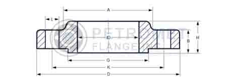
| Nominal Pipe Size |
Dia of holes (L) |
Diameter of Hub at base (A) |
Diameter of raised face (G) |
Outside diameter of flange (D) |
Thick of flange (B) |
Length thru Hub (H) |
Dia of bore (ID) |
Dia of bolts |
No of holes |
Diam of bolt circle (K) |
Approx weight kg |
|---|---|---|---|---|---|---|---|---|---|---|---|
| 1/2 | 15.7 | 35.1 | 30.2 | 88.9 | 11.2 | 15.7 | 22.4 | 1/2 | 4 | 60.5 | 0.5 |
| 3/4 | 15.7 | 42.9 | 38.1 | 98.6 | 12.7 | 15.7 | 27.7 | 1/2 | 4 | 69.9 | 1 |
| 1 | 15.7 | 50.8 | 49.3 | 108 | 14.2 | 17.5 | 34.5 | 1/2 | 4 | 79.2 | 1 |
| 1-1/4 | 15.7 | 63.5 | 58.7 | 117.3 | 15.7 | 20.6 | 43.2 | 1/2 | 4 | 88.9 | 1 |
| 1-1/2 | 15.7 | 73.2 | 65 | 127 | 17.5 | 22.4 | 49.5 | 1/2 | 4 | 98.6 | 1 |
| 2 | 19.1 | 91.9 | 77.7 | 152.4 | 19.1 | 25.4 | 62 | 5/8 | 4 | 120.7 | 2 |
| 2-1/2 | 19.1 | 104.6 | 90.4 | 177.8 | 22.4 | 28.4 | 74.7 | 5/8 | 4 | 139.7 | 3 |
| 3 | 19.1 | 127 | 108 | 190.5 | 23.9 | 30.2 | 90.7 | 5/8 | 4 | 152.4 | 4 |
| 3-1/2 | 19.1 | 139.7 | 122.2 | 215.9 | 23.9 | 31.8 | 103.4 | 5/8 | 8 | 177.8 | 5 |
| 4 | 19.1 | 157.2 | 134.9 | 228.6 | 23.9 | 33.3 | 116.1 | 5/8 | 8 | 190.5 | 6 |
| 5 | 22.4 | 185.7 | 163.6 | 254 | 23.9 | 36.6 | 143.8 | 3/4 | 8 | 215.9 | 7 |
| 6 | 22.4 | 215.9 | 192 | 279.4 | 25.4 | 39.6 | 170.7 | 3/4 | 8 | 241.3 | 9 |
| 8 | 22.4 | 269.7 | 246.1 | 342.9 | 28.4 | 44.5 | 221.5 | 3/4 | 8 | 298.5 | 14 |
| 10 | 25.4 | 323.9 | 304.8 | 406.4 | 30.2 | 49.3 | 276.4 | 7/8 | 12 | 362 | 20 |
| 12 | 25.4 | 381 | 365.3 | 482.6 | 31.8 | 55.6 | 327.2 | 7/8 | 12 | 431.8 | 29 |
| 14 | 28.4 | 412.8 | 400.1 | 533.4 | 35.1 | 57.2 | 359.2 | 1 | 12 | 476.3 | 41 |
| 16 | 28.4 | 469.9 | 457.2 | 596.9 | 36.6 | 63.5 | 410.5 | 1 | 16 | 539.8 | 44 |
| 18 | 31.8 | 533.4 | 505 | 635 | 39.6 | 68.3 | 461.8 | 1-1/8 | 16 | 577.9 | 59 |
| 20 | 31.8 | 584.2 | 558.8 | 698.5 | 42.9 | 73.2 | 513.1 | 1-1/8 | 20 | 635 | 75 |
| 24 | 35.1 | 692.2 | 663.4 | 812.8 | 47.8 | 82.6 | 616 | 1-1/4 | 20 | 749.3 | 100 |
300 Lb Slip On Flange Dimensions
| Nominal Pipe Size |
Diameter of Hub at base (A) |
Outside diameter of flange (D) |
Diam of bolt circle (K) |
Thick of flange (B) |
Length thru Hub (H) |
Dia of bore (ID) |
No of holes |
Dia of holes (L) |
Diameter of raised face (G) |
Dia of bolts |
Approx weight kg |
|---|---|---|---|---|---|---|---|---|---|---|---|
| 1/2 | 35.1 | 95.3 | 66.5 | 14.2 | 22.4 | 22.4 | 4 | 15.7 | 38.1 | 1/2 | 1 |
| 3/4 | 42.9 | 117.3 | 82.6 | 15.7 | 25.4 | 27.7 | 4 | 19.1 | 47.8 | 5/8 | 1 |
| 1 | 50.8 | 124 | 88.9 | 17.5 | 26.9 | 34.5 | 4 | 19.1 | 53.8 | 5/8 | 1 |
| 1-1/4 | 63.5 | 133.4 | 98.6 | 19.1 | 26.9 | 43.2 | 4 | 19.1 | 63.5 | 5/8 | 2 |
| 1-1/2 | 73.2 | 155.4 | 114.3 | 20.6 | 30.2 | 49.5 | 4 | 22.4 | 69.9 | 3/4 | 3 |
| 2 | 91.9 | 165.1 | 127 | 22.4 | 33.3 | 62 | 8 | 19.1 | 84.1 | 5/8 | 3 |
| 2-1/2 | 104.6 | 190.5 | 149.4 | 25.4 | 38.1 | 74.7 | 8 | 22.4 | 100.1 | 3/4 | 5 |
| 3 | 127 | 209.6 | 168.1 | 28.4 | 42.9 | 90.7 | 22.4 | 8 | 117.3 | 3/4 | 6 |
| 3-1/2 | 139.7 | 228.6 | 184.2 | 30.2 | 44.5 | 103.4 | 22.4 | 8 | 133.4 | 3/4 | 8 |
| 4 | 157.2 | 254 | 200.2 | 31.8 | 47.8 | 116.1 | 8 | 22.4 | 146.1 | 3/4 | 10 |
| 5 | 185.7 | 279.4 | 235 | 35.1 | 50.8 | 143.8 | 8 | 22.4 | 177.8 | 3/4 | 13 |
| 6 | 215.9 | 317.5 | 269.7 | 36.6 | 52.3 | 170.7 | 12 | 22.4 | 206.2 | 3/4 | 18 |
| 8 | 269.7 | 381 | 330.2 | 41.1 | 62 | 221.5 | 12 | 25.4 | 260.4 | 73/93 | 26 |
| 10 | 323.9 | 444.5 | 387.4 | 47.8 | 66.5 | 276.4 | 16 | 28.4 | 320.5 | 1 | 37 |
| 12 | 381 | 520.7 | 450.9 | 50.8 | 73.2 | 327.2 | 16 | 31.8 | 374.7 | 1-1/8 | 52 |
| 14 | 412.8 | 584.2 | 514.4 | 53.8 | 76.2 | 359.2 | 20 | 31.8 | 425.5 | 1-1/8 | 75 |
| 16 | 469.9 | 647.7 | 571.5 | 57.2 | 82.6 | 410.5 | 20 | 35.1 | 482.6 | 1-1/4 | 86 |
| 18 | 533.4 | 711.2 | 628.7 | 60.5 | 88.9 | 461.8 | 24 | 35.1 | 533.4 | 1-1/4 | 113 |
| 20 | 584.2 | 774.7 | 685.8 | 63.5 | 95.3 | 513.1 | 24 | 35.1 | 587.2 | 1-1/4 | 143 |
| 24 | 692.2 | 914.4 | 812.8 | 69.9 | 106.4 | 616 | 24 | 41.1 | 701.5 | 1-1/2 | 215 |
Buy raised/ flat face Alloy Steel Threaded Slip On Flange and Ductile Iron Hubbed Slip On Flanges at Unbeatable Prices in Mumbai
Class 600 Slip On Flange Dimensions
| Nominal Pipe Size |
Length thru Hub (H) |
Outside diameter of flange (D) |
Diameter of Hub at base (A) |
Diameter of raised face (G) |
Dia of bore (ID) |
Thick of flange (B) |
No of holes |
Dia of holes (L) |
Diam of bolt circle (K) |
Dia of bolts |
Approx weight kg |
|---|---|---|---|---|---|---|---|---|---|---|---|
| 1/2 | 22.4 | 95.3 | 35.1 | 38.1 | 22.4 | 14.2 | 4 | 15.7 | 66.5 | 1/2 | 1 |
| 3/4 | 25.4 | 117.3 | 42.9 | 47.8 | 27.7 | 15.7 | 4 | 19.1 | 82.6 | 5/8 | 1 |
| 1 | 26.9 | 124 | 50.8 | 53.8 | 34.5 | 17.5 | 4 | 19.1 | 88.9 | 5/8 | 2 |
| 1-1/4 | 28.4 | 133.4 | 63.5 | 63.5 | 43.2 | 20.6 | 4 | 19.1 | 98.6 | 5/8 | 2 |
| 1-1/2 | 31.8 | 155.4 | 73.2 | 69.9 | 49.5 | 22.4 | 4 | 22.4 | 114.3 | 3/4 | 3 |
| 2 | 36.6 | 165.1 | 91.9 | 84.1 | 62 | 25.4 | 8 | 19.1 | 127 | 5/8 | 4 |
| 2-1/2 | 41.1 | 190.5 | 104.6 | 100.1 | 74.7 | 28.4 | 8 | 22.4 | 149.4 | 3/4 | 6 |
| 3 | 46 | 209.6 | 127 | 117.3 | 90.7 | 31.8 | 8 | 22.4 | 168.1 | 3/4 | 7 |
| 3-1/2 | 49.3 | 228.6 | 139.7 | 133.4 | 103.4 | 35.1 | 8 | 25.4 | 184.2 | 7/8 | 10 |
| 4 | 53.8 | 273.1 | 157.2 | 152.4 | 116.1 | 38.1 | 8 | 25.4 | 215.9 | 7/8 | 17 |
| 5 | 60.5 | 330.2 | 185.7 | 189 | 143.8 | 44.5 | 8 | 28.4 | 266.7 | 1 | 29 |
| 8 | 76.2 | 419.1 | 269.7 | 273.1 | 221.5 | 55.6 | 12 | 31.8 | 349.3 | 1-1/8 | 52 |
| 10 | 85.9 | 508 | 323.9 | 342.9 | 276.4 | 63.5 | 16 | 35.1 | 431.8 | 1-1/4 | 77 |
| 12 | 91.9 | 558.8 | 381 | 400.1 | 327.2 | 66.5 | 20 | 35.1 | 489 | 1-1/4 | 91 |
| 14 | 93.7 | 603.3 | 412.8 | 431.8 | 359.2 | 69.9 | 20 | 38.1 | 527.1 | 1-3/8 | 104 |
| 16 | 106.4 | 685.8 | 469.9 | 495.3 | 410.5 | 76.2 | 20 | 41.1 | 603.3 | 1-1/2 | 150 |
| 18 | 117.3 | 743 | 533.4 | 546.1 | 461.8 | 82.6 | 20 | 44.5 | 654.1 | 1-5/8 | 181 |
| 20 | 127 | 812.8 | 584.2 | 609.6 | 513.1 | 88.9 | 24 | 44.5 | 723.9 | 1-5/8 | 231 |
| 24 | 139.7 | 939.8 | 692.2 | 717.6 | 616 | 101.6 | 24 | 50.8 | 838.2 | 1-7/8 | 331 |
Class 900 Slip On Flange Dimensions
| Nominal Pipe Size |
Dia of bore (ID) |
Thick of flange (B) |
Outside diameter of flange (D) |
Diameter of Hub at base (A) |
Diameter of raised face (G) |
No of holes |
Dia of holes (L) |
Length thru Hub (H) |
Diam of bolt circle (K) |
Dia of bolts |
Approx weight kg |
|---|---|---|---|---|---|---|---|---|---|---|---|
| 1/2 | 22.4 | 22.4 | 120.7 | 35.1 | 38.1 | 4 | 22.4 | 31.8 | 82.6 | 3/4 | 2 |
| 3/4 | 27.7 | 25.4 | 130 | 42.9 | 44.5 | 4 | 22.4 | 35.1 | 88.9 | 3/4 | 2 |
| 1 | 34.5 | 28.4 | 149.4 | 50.8 | 52.3 | 4 | 25.4 | 41.1 | 101.6 | 7/8 | 4 |
| 1-1/4 | 43.2 | 28.4 | 158.8 | 63.5 | 63.5 | 4 | 25.4 | 41.1 | 111.3 | 7/8 | 4 |
| 1-1/2 | 49.5 | 31.8 | 177.8 | 73.2 | 69.9 | 4 | 28.4 | 44.5 | 124 | 1 | 5 |
| 2 | 62 | 38.1 | 215.9 | 91.9 | 104.6 | 8 | 25.4 | 57.2 | 165.1 | 7/8 | 11 |
| 2-1/2 | 74.7 | 41.1 | 244.3 | 104.6 | 124 | 8 | 28.4 | 63.5 | 190.5 | 1 | 16 |
| 3 | 90.7 | 38.1 | 241.3 | 127 | 127 | 8 | 25.4 | 53.8 | 190.5 | 7/8 | 12 |
| 4 | 116.1 | 44.5 | 292.1 | 157.2 | 158.8 | 8 | 31.8 | 69.9 | 235 | 1-1/8 | 24 |
| 5 | 143.8 | 50.8 | 349.3 | 185.7 | 190.5 | 8 | 35.1 | 79.2 | 279.4 | 1-1/4 | 38 |
| 6 | 170.7 | 55.6 | 381 | 215.9 | 235 | 31.8 | 12 | 85.9 | 317.5 | 1-1/8 | 50 |
| 8 | 221.5 | 63.5 | 469.9 | 269.7 | 298.5 | 12 | 38.1 | 101.6 | 393.7 | 1-3/8 | 77 |
| 10 | 276.4 | 69.9 | 546.1 | 323.9 | 368.3 | 16 | 38.1 | 108 | 469.9 | 1-3/8 | 111 |
| 12 | 327.2 | 79.2 | 609.6 | 381 | 419.1 | 20 | 38.1 | 117.3 | 533.4 | 1-3/8 | 147 |
| 14 | 359.2 | 85.9 | 641.4 | 412.8 | 450.9 | 20 | 41.1 | 130 | 558.8 | 1-1/2 | 181 |
| 16 | 410.5 | 88.9 | 704.9 | 469.9 | 508 | 20 | 44.5 | 133.4 | 41.3 | 1-5/8 | 616 |
| 18 | 461.8 | 101.6 | 787.4 | 533.4 | 565.2 | 20 | 50.8 | 152.4 | 685.8 | 1-7/8 | 272 |
| 20 | 513.1 | 108 | 857.3 | 584.2 | 622.3 | 20 | 53.8 | 158.8 | 749.3 | 2 | 331 |
| 24 | 616 | 139.7 | 1041.4 | 692.2 | 749.3 | 20 | 66.5 | 203.2 | 901.7 | 2-1/2 | 635 |
Class 1500 Slip On Flange Dimensions
| Nominal Pipe Size |
Thick of flange (B) |
Outside diameter of flange (D) |
Diameter of raised face (G) |
Diam of bolt circle (K) |
Length thru Hub (H) |
Dia of bore (ID) |
Diameter of Hub at base (A) |
No of holes |
Dia of holes (L) |
Dia of bolts |
Approx weight kg |
|---|---|---|---|---|---|---|---|---|---|---|---|
| 1/2 | 22.4 | 120.7 | 38.1 | 82.6 | 31.8 | 22.4 | 35.1 | 4 | 22.4 | 3/4 | 2 |
| 3/4 | 25.4 | 130 | 44.5 | 88.9 | 35.1 | 27.7 | 42.9 | 4 | 22.4 | 3/4 | 2 |
| 1 | 28.4 | 149.4 | 52.3 | 101.6 | 41.1 | 34.5 | 50.8 | 4 | 25.4 | 7/8 | 4 |
| 1-1/4 | 28.4 | 158.8 | 63.5 | 111.3 | 41.1 | 43.2 | 63.5 | 4 | 25.4 | 7/8 | 4 |
| 1-1/2 | 31.8 | 177.8 | 69.9 | 124 | 44.5 | 49.5 | 73.2 | 4 | 28.4 | 1 | 5 |
| 2 | 38.1 | 215.9 | 104.6 | 165.1 | 57.2 | 62 | 91.9 | 8 | 25.4 | 7/8 | 11 |
| 2-1/2 | 41.1 | 244.3 | 124 | 190.5 | 63.5 | 74.7 | 104.6 | 8 | 28.4 | 1 | 16 |
| 3 | 47.8 | 266.7 | 133.4 | 203.2 | 73.2 | - | 127 | 8 | 31.8 | 1-1/8 | 22 |
| 4 | 53.8 | 311.2 | 162.1 | 241.3 | 90.4 | - | 157.2 | 8 | 35.1 | 1-1/4 | 33 |
| 5 | 73.2 | 374.7 | 196.9 | 292.1 | 104.6 | - | 185.7 | 8 | 41.1 | 1-1/2 | 59 |
| 6 | 82.6 | 393.7 | 228.6 | 317.5 | 119.1 | - | 215.9 | 12 | 38.1 | 1-3/8 | 75 |
| 8 | 91.9 | 482.6 | 292.1 | 393.7 | 142.7 | - | 269.7 | 12 | 44.5 | 1-5/8 | 118 |
| 10 | 108 | 584.2 | 368.3 | 482.6 | 158.8 | - | 323.9 | 12 | 50.8 | 1-7/8 | 197 |
| 12 | 124 | 673.1 | 450.9 | 571.5 | 180.8 | - | 381 | 16 | 53.8 | 2 | 263 |
| 14 | 133.4 | 749.3 | 495.3 | 635 | - | - | 412.8 | 16 | 60.5 | 2-1/4 | - |
| 16 | 146.1 | 825.5 | 552.5 | 704.9 | - | - | 469.9 | 16 | 66.5 | 2-1/2 | - |
| 18 | 162.1 | 914.4 | 596.9 | 774.7 | - | - | 533.4 | 16 | 73.2 | 2-3/4 | - |
| 20 | 177.8 | 984.3 | 641.4 | 831.9 | - | - | 584.2 | 16 | 79.2 | 3 | - |
| 24 | 203.2 | 1168.4 | 762 | 990.6 | - | - | 692.2 | 16 | 91.9 | 3-1/2 | - |
Class 2500 Slip On Flange Dimensions
| Nominal Pipe Size | Outside Diameter (O) | Thickness (T) | Raised Face Diameter (R) | Length Thru Hub (Y) | Hub Diameter (X) | Bore (B) | Approximate Weight (lbs) | Bolt Circle (C) | Number of Holes | Diameter of Holes |
|---|---|---|---|---|---|---|---|---|---|---|
| 1/2 | 5.25 | 1.19 | 1.38 | 1.56 | 1.69 | 0.88 | 7 | 3.50 | 4 | 0.88 |
| 3/4 | 5.50 | 1.25 | 1.69 | 1.69 | 2.00 | 1.09 | 8 | 3.75 | 4 | 0.88 |
| 1 | 6.25 | 1.38 | 2.00 | 1.88 | 2.25 | 1.36 | 11 | 4.25 | 4 | 1.00 |
| 1 1/4 | 7.25 | 1.50 | 2.50 | 2.06 | 2.88 | 1.70 | 16 | 5.13 | 4 | 1.13 |
| 1 1/2 | 8.00 | 1.75 | 2.88 | 2.38 | 3.13 | 1.95 | 22 | 5.75 | 4 | 1.25 |
| 2 | 9.25 | 2.00 | 3.63 | 2.75 | 3.75 | 2.44 | 38 | 6.75 | 8 | 1.13 |
| 2 1/2 | 10.50 | 2.25 | 4.13 | 3.13 | 4.50 | 2.94 | 55 | 7.75 | 8 | 1.25 |
| 3 | 12.00 | 2.63 | 5.00 | 3.63 | 5.25 | 3.57 | 83 | 9.00 | 8 | 1.38 |
| 4 | 14.00 | 3.00 | 6.19 | 4.25 | 6.50 | 4.57 | 125 | 10.75 | 8 | 1.63 |
| 5 | 16.50 | 3.63 | 7.31 | 5.13 | 8.00 | 5.66 | 210 | 12.75 | 8 | 1.88 |
| 6 | 19.00 | 4.25 | 8.50 | 6.00 | 9.25 | 6.72 | 325 | 14.50 | 8 | 2.13 |
| 8 | 21.75 | 5.00 | 10.63 | 7.00 | 12.00 | 8.72 | 485 | 17.25 | 12 | 2.13 |
| 10 | 26.50 | 6.50 | 12.75 | 9.00 | 14.75 | 10.88 | 930 | 21.25 | 12 | 2.63 |
| 12 | 30.00 | 7.25 | 15.00 | 10.00 | 17.38 | 12.88 | 1100 | 24.38 | 12 | 2.88 |
Check 316 Stainless Steel Slip On Joint Flange and ASTM A182 F304 Reducing Slip On Flange torque chart & price in Mumbai
Pn16 Slip On Flange Weights
| Size mm | Size in | O.D. in | I.D. in | O.D. mm | I.D. mm | Ø B.H.C. in | THK in | Ø B.H. in | Ø B.H. mm | # B.H. | Ø B.H.C. mm | THK mm | Weight lb | Weight kg |
| 200 | 8 | 13.39 | 8.72 | 340 | 221.5 | 11.61 | 1.03 | 0.87 | 22 | 12 | 295 | 26 | 22.0 | 10.0 |
| 250 | 10 | 15.94 | 10.89 | 405 | 276.5 | 13.98 | 1.15 | 1.02 | 26 | 12 | 355 | 29 | 31.5 | 14.3 |
| 300 | 12 | 18.11 | 12.89 | 460 | 327.5 | 16.14 | 1.26 | 1.02 | 26 | 12 | 410 | 32 | 42.0 | 19.1 |
| 350 | 14 | 20.47 | 14.15 | 520 | 359.0 | 18.50 | 1.38 | 1.02 | 26 | 16 | 470 | 35 | 62.5 | 28.4 |
| 400 | 16 | 22.83 | 16.18 | 580 | 411.0 | 20.67 | 1.50 | 1.18 | 30 | 16 | 525 | 38 | 79.5 | 36.1 |
| 450 | 18 | 25.20 | 18.19 | 640 | 462.0 | 23.03 | 1.66 | 1.18 | 30 | 20 | 585 | 42 | 102.0 | 46.3 |
| 500 | 20 | 28.15 | 20.22 | 715 | 513.5 | 25.59 | 1.82 | 1.30 | 33 | 20 | 650 | 46 | 142.0 | 64.5 |
| 600 | 24 | 33.07 | 24.27 | 840 | 616.5 | 30.31 | 2.17 | 1.42 | 36 | 20 | 770 | 55 | 224.5 | 101.9 |
| 700 | 28 | 35.83 | 28.19 | 910 | 716.0 | 33.07 | 2.48 | 1.42 | 36 | 24 | 840 | 63 | 243.5 | 110.5 |
| 800 | 32 | 40.35 | 32.19 | 1025 | 817.6 | 37.40 | 2.92 | 1.54 | 39 | 24 | 950 | 74 | 347.5 | 157.8 |
| 900 | 36 | 44.29 | 35.19 | 1125 | 893.8 | 41.34 | 3.23 | 1.54 | 39 | 28 | 1050 | 82 | 472.0 | 214.3 |
| 1000 | 40 | 49.41 | 39.19 | 1255 | 995.4 | 46.06 | 3.55 | 1.65 | 42 | 28 | 1170 | 90 | 655.0 | 297.4 |
Slip On Reducing Flange Weight Chart
| NPS (Inches) |
DN (mm) |
FLANGE OD A MM |
FLANGE THICKNESS D MM |
SLIP ON FLANGE WEIGHT (KGS) |
| 1/ 2 | 15 | 88.9 | 11.2 | 0.4 |
| 3/ 4 | 20 | 98.6 | 12.7 | 0.6 |
| 1 | 25 | 108 | 14.2 | 0.8 |
| 1 1/ 4 | 32 | 117.3 | 15.7 | 1 |
| 1 1/ 2 | 40 | 127 | 17.5 | 1.3 |
| 2 | 50 | 152.4 | 19.1 | 2.1 |
| 2 1/ 2 | 65 | 177.8 | 22.4 | 3.3 |
| 3 | 80 | 190.5 | 23.9 | 3.9 |
| 3 1/ 2 | 90 | 215.9 | 23.9 | 4.8 |
| 4 | 100 | 228.6 | 23.9 | 5.3 |
| 5 | 125 | 254 | 23.9 | 6.1 |
| 6 | 150 | 279.4 | 25.4 | 7.5 |
| 8 | 200 | 342.9 | 28.4 | 12.1 |
| 10 | 250 | 406.4 | 30.2 | 16.5 |
| 12 | 300 | 482.6 | 31.8 | 26.2 |
| 14 | 350 | 533.4 | 35.1 | 34.6 |
| 16 | 400 | 596.9 | 36.6 | 44.8 |
| 18 | 450 | 635 | 39.6 | 48.9 |
| 20 | 500 | 698.5 | 42.9 | 61.9 |
| 24 | 600 | 812.8 | 47.8 | 86.9 |
PN10 Slip On Flange Dimensions
| Size mm | Size in | O.D. mm | O.D. in | I.D. in | I.D. mm | Ø B.H.C. in | Ø B.H.C. mm | Ø B.H. In | Ø B.H. mm | # B.H. | THK in | THK mm | Weight lb | Weight kg | ||||||||
| 25 | 1.00 | 115 | 4.53 | 1.36 | 34.5 | 3.35 | 85 | 0.55 | 14 | 4 | 0.630 | 16 | 2.5 | 1.1 | ||||||||
| 32 | 1.25 | 140 | 5.51 | 1.71 | 43.5 | 3.94 | 100 | 0.71 | 18 | 4 | 0.710 | 18 | 4.1 | 1.9 | ||||||||
| 40 | 1.50 | 150 | 5.91 | 1.95 | 49.5 | 4.33 | 110 | 0.71 | 18 | 4 | 0.710 | 18 | 4.6 | 2.1 | ||||||||
| 50 | 2.00 | 165 | 6.50 | 2.42 | 61.5 | 4.92 | 125 | 0.71 | 18 | 4 | 0.790 | 20 | 6.1 | 2.8 | ||||||||
| 65 | 2.50 | 185 | 7.28 | 3.05 | 77.5 | 5.71 | 145 | 0.71 | 18 | 4 | 0.790 | 20 | 7.3 | 3.3 | ||||||||
| 80 | 3.00 | 200 | 7.87 | 3.56 | 90.5 | 6.30 | 160 | 0.71 | 18 | 8 | 0.790 | 20 | 8.0 | 3.6 | ||||||||
| 100 | 4.00 | 220 | 8.66 | 4.57 | 116.0 | 7.09 | 180 | 0.71 | 18 | 8 | 0.870 | 22 | 9.7 | 4.4 | ||||||||
| 125 | 5.00 | 250 | 9.84 | 5.57 | 141.5 | 8.27 | 210 | 0.71 | 18 | 8 | 0.870 | 22 | 12.0 | 5.4 | ||||||||
| 150 | 6.00 | 285 | 11.22 | 6.71 | 170.4 | 9.45 | 240 | 0.87 | 22 | 8 | 0.950 | 24 | 16.0 | 7.3 | ||||||||
| 200 | 8.00 | 340 | 13.39 | 8.72 | 221.5 | 11.61 | 295 | 0.87 | 22 | 8 | 0.950 | 24 | 21.0 | 9.5 | ||||||||
| 250 | 10.00 | 395 | 15.55 | 10.89 | 276.5 | 13.78 | 350 | 0.87 | 22 | 12 | 1.024 | 26 | 26.5 | 12.0 | ||||||||
| 300 | 12.00 | 445 | 17.52 | 12.89 | 327.5 | 15.75 | 400 | 0.87 | 22 | 12 | 1.024 | 26 | 30.5 | 13.8 | ||||||||
| 350 | 14.00 | 505 | 19.88 | 14.15 | 359.5 | 18.11 | 460 | 0.87 | 22 | 16 | 1.181 | 30 | 48.0 | 21.8 | ||||||||
| 400 | 16.00 | 565 | 22.24 | 16.18 | 411.0 | 20.28 | 515 | 1.02 | 26 | 16 | 1.260 | 32 | 61.0 | 27.7 | ||||||||
| 450 | 18.00 | 615 | 24.21 | 18.19 | 462.0 | 22.24 | 565 | 1.02 | 26 | 20 | 1.417 | 36 | 74.5 | 33.8 | ||||||||
| 500 | 20.00 | 670 | 26.38 | 20.22 | 513.5 | 24.41 | 620 | 1.02 | 26 | 20 | 1.496 | 38 | 89.0 | 40.4 | ||||||||
| 600 | 24.00 | 780 | 30.71 | 24.27 | 616.5 | 28.54 | 725 | 1.18 | 30 | 20 | 1.654 | 42 | 120.0 | 54.5 | ||||||||
| 700 | 28.00 | 895 | 35.24 | 28.19 | 716.0 | 33.07 | 840 | 1.18 | 30 | 24 | 1.969 | 50 | 181.5 | 82.4 | ||||||||
| 800 | 32.00 | 1015 | 39.96 | 32.19 | 817.6 | 37.40 | 950 | 1.30 | 33 | 24 | 2.200 | 56 | 254.5 | 115.5 | ||||||||
| 900 | 36.00 | 1115 | 43.90 | 35.19 | 893.8 | 41.34 | 1050 | 1.30 | 33 | 28 | 2.440 | 62 | 348.5 | 158.2 | ||||||||
| 1000 | 40.00 | 1230 | 48.43 | 39.19 | 995.4 | 45.67 | 1160 | 1.42 | 36 | 28 | 2.760 | 70 | 462.5 | 210.0 | ||||||||
Buy Stainless Steel SA 182 F316 Slip On Flange and Mild Steel SORF Flange for leak-proof connection, manufacturer of Alloy Steel Slip On Backing Flange and ASTM A516 Gr.70 Slip On Joint Flange in India
MS Slipon Flange Weight Chart
| NOMINAL SIZE | DIMENSIONS | WEIGHT (KG) | ||
|---|---|---|---|---|
| NPS (Inches) |
DN (mm) | FLANGE OD A MM |
FLANGE THICKNESS D MM |
SOW SW |
| 1/2 | 15 | 95.3 | 14.2 | 0.6 |
| 3/4 | 20 | 117.3 | 15.7 | 1.1 |
| 1 | 25 | 124 | 17.5 | 1.4 |
| 1 1/4 | 32 | 133.4 | 19.1 | 1.7 |
| 1 1/2 | 40 | 155.5 | 20.6 | 2.5 |
| 2 | 50 | 165.1 | 22.4 | 2.9 |
| 2 1/2 | 65 | 190.5 | 25.4 | 4.3 |
| 3 | 80 | 215.9 | 28.4 | 5.9 |
| 3 1/2 | 90 | 228.6 | 30.2 | 7.3 |
| 4 | 100 | 254 | 31.8 | 9.6 |
| 5 | 125 | 279.4 | 35.1 | 12.3 |
| 6 | 150 | 317.5 | 36.6 | 15.6 |
| 8 | 200 | 381 | 41.1 | 24.2 |
| 10 | 250 | 444.5 | 47.6 | 34.1 |
| 12 | 300 | 520.7 | 50.8 | 49.8 |
| 14 | 350 | 584.2 | 53.8 | 69.9 |
| 16 | 400 | 647.7 | 57.2 | 88.1 |
| 18 | 450 | 711.2 | 60.5 | 109.0 |
| 20 | 500 | 774.7 | 63.5 | 134.0 |
| 24 | 600 | 914.4 | 70.0 | 201.0 |
Stainless Steel Slip On Flange Weight
| NOMINAL SIZE | DIMENSIONS | WEIGHT (KG) | ||||
|---|---|---|---|---|---|---|
| NPS (Inches) |
DN (mm) | FLANGE MM |
FLANGE THICKNESS |
SOW SW |
WN | BLIND |
| 1/2 | 15 | 88.9 | 11.2 | 0.4 | 0.5 | 0.4 |
| 3/4 | 20 | 98.6 | 12.7 | 0.6 | 0.7 | 0.6 |
| 1 | 25 | 108 | 14.2 | 0.8 | 1 | 0.9 |
| 1 1/4 | 32 | 117.3 | 15.7 | 1 | 1.3 | 1.2 |
| 1 1/2 | 40 | 127 | 17.5 | 1.3 | 1.7 | 1.5 |
| 2 | 50 | 152.4 | 19.1 | 2.1 | 2.6 | 2.4 |
| 2 1/2 | 65 | 177.8 | 22.4 | 3.3 | 4.1 | 3.9 |
| 3 | 80 | 190.5 | 23.9 | 3.9 | 4.9 | 4.9 |
| 3 1/2 | 90 | 215.9 | 23.9 | 4.8 | 6.1 | 6.2 |
| 4 | 100 | 228.6 | 23.9 | 5.3 | 6.8 | 7.0 |
| 5 | 125 | 254 | 23.9 | 6.1 | 8.6 | 8.6 |
| 6 | 150 | 279.4 | 25.4 | 7.5 | 10.6 | 11.3 |
| 8 | 200 | 342.9 | 28.4 | 12.1 | 17.6 | 19.6 |
| 10 | 250 | 406.4 | 30.2 | 16.5 | 24 | 28.6 |
| 12 | 300 | 482.6 | 31.8 | 26.2 | 36.5 | 43.2 |
| 14 | 350 | 533.4 | 35.1 | 34.6 | 48.4 | 58.1 |
| 16 | 400 | 596.9 | 36.6 | 44.8 | 60.6 | 76.1 |
| 18 | 450 | 635 | 39.6 | 48.9 | 68.3 | 93.7 |
| 20 | 500 | 698.5 | 42.9 | 61.9 | 84.5 | 122.0 |
| 24 | 600 | 812.8 | 47.8 | 86.9 | 115 | 185.0 |
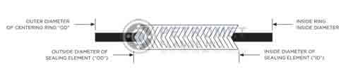
Slip On Flange Gasket
Style WR & WRI to suit ASME / ANSI B16.5 and Slip-On Flanges
|
Class 150-1500 |
Guide Ring Outside Diameter | |||||
|---|---|---|---|---|---|---|
| Nom.
Pipe Size |
Inner
Ring I.D. |
Winding | Class
150 |
Class
300-600 |
Class
900-1500 |
|
| I.D. | O.D. | |||||
| 1/4 | 0.562 | 0.875 | 1.750 | 1.750 | ||
| 1/2 | 0.562 | 0.937 | 1.250 | 1.875 | 2.125 | 2.500 |
| 3/4 | 0.812 | 1.187 | 1.562 | 2.250 | 2.625 | 2.750 |
| 1 | 1.062 | 1.437 | 1.875 | 2.625 | 2.875 | 3.125 |
| 1 1/4 | 1.375 | 1.875 | 2.375 | 3.000 | 3.250 | 3.500 |
| 1 1/2 | 1.625 | 2.125 | 2.750 | 3.375 | 3.250 | 3.875 |
Slip On Flange Pressure and Temperature Ratings
| Pressure Class # | Service Temp (°F) | Carbon Steel | Cr - Mo | SS 304 | SS 316 | SS 304L SS 316L | SS 321 |
| 150# | 100 | 285 | 290 | 275 | 275 | 230 | 275 |
| 150# | 200 | 260 | 260 | 235 | 240 | 195 | 235 |
| 150# | 300 | 230 | 230 | 205 | 215 | 175 | 210 |
| 150# | 400 | 200 | 200 | 180 | 195 | 160 | 190 |
| 150# | 500 | 170 | 170 | 170 | 170 | 145 | 170 |
| 150# | 600 | 140 | 140 | 140 | 140 | 140 | 140 |
| 150# | 650 | 125 | 125 | 125 | 125 | 125 | 125 |
| 150# | 700 | 110 | 110 | 110 | 110 | 110 | 110 |
| 150# | 750 | 95 | 95 | 95 | 95 | 95 | 95 |
| 150# | 800 | 80 | 80 | 80 | 80 | 80 | 80 |
| 150# | 850 | 65 | 65 | 65 | 65 | 65 | 65 |
| 150# | 900 | 50 | 50 | 50 | 50 | 50 | |
| 150# | 950 | 35 | 35 | 35 | 35 | 35 | |
| 150# | 1000 | 20 | 20 | 20 | 20 | 20 |
Features of Stainless Steel Slip On Flange
- These are less expensive flanges.
- They have a low hub because the pipe slips into the flange before welding.
- Internally and externally, slip-on flanges are simple to align and weld.
- SORF If Type B or Type C ends are used, flanges can also be used as lap-joint flanges.
- Assembly and installation are simple.
- They take up the smallest amount of longitudinal area for a flange.
Applications of Carbon Steel Slip On Flange
- Nuclear Power
- Power Plants
- Oil & Gas Industry
- Ship Building
- Refineries
- Marine Applications
- Fossil Fuel Power Plants
- Paper & Pulp
- Industrial Boilers
Facing Types of Slip On Pipe Flange
Raised Face Slip On Flange
RTJ Slip On Pipe Flanges
How To Weld Slip On Flange
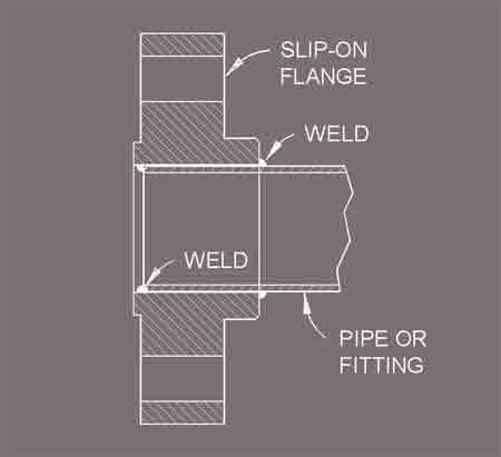
The gap separation for welding a flange, fitting, or piece of pipe together is determined by the Welding Qualification. A 1/16" spacing is required by API Std 1104 (Standard for Welding of Pipelines and Related Facilities). When welding a slip-on flange, the pipe or fitting is set back from the flange face by the amount of wall thickness -0" +1/16".
Flanges Types
Pipe Fittings Material
Flanges Material
Other Products