
- Call : +91 22 67436442
- exports@petrometflange.com
Stainless Steel Blind Flange
- Home /
- Stainless Steel Blind Flange
Looking for Blind Flange manufacturers in India in Class 150/ 300/ 600 ? We produce BLRF Flange in Carbon Steel, SS, Hastelloy, Nickel, Inconel, AS, Copper, Titanium and Aluminium Alloy
What is a Blind Flange?
The blind flange can be described as a flange without a hub or a bore in the center. They come with the same face thickness as that of a flange, along with a matching face type and a bolting pattern which is also quite similar. The blind flanges are used for sealing the ends of a pipe or the open nozzle of a pressure vessel. They are bolted to the pipes, which helps in providing easy access to the interior unlike a welded flange or cap.
The blind flange is a solid disk without any holes or openings, this prevents any liquid or gas from passing through it. The blind flange is placed between two flanges so as to stop the flow through the pipe. They help in performing repairs and maintenance inside the pipeline, by shutting off the pipe run easily. It also helps in speeding up the process of constructing a pipeline.
What is Carbon steel blind flange Face Types
Carbon steel blind flange, just like any other flange, comes with two types of faces, namely raised face and flat face.
What is the difference between blank and blind flange?
A blank flange can be described as a thin plate that is placed in between two flanges in the piping system, so as to stop the flow the pipe runs. Whereas, the blind flange is a thick solid plate with no hubs or bore in the middle but bolted holes throughout its perimeter. It helps to stop the flow at the end of the pipe.
Where is Stainless Steel Blind Flange used?
The Where is Stainless Steel Blind Flanges are used for sealing the ends of the pipes or the nozzle of the pressure vessel. They help to cut off the connection of a pipe, and also comes in handy when inspection or maintenance and repair works need to be carried out inside the piping system. The material grade of the flange is temperature and corrosion resistant, with high tensile strength and durability. Thus, they can be used for high temperature and pressure applications.
Blind Flanges for Hydro test
The hydro test for blind flanges is carried out so as to check its structural integrity. This is a type of pressure test, wherein the flanges are pressured to see if they are leaking. It helps to understand the strength of the flange.

Stainless Steel Blind Flange
European Directive 2014/68/eu certified ASTM A105 Carbon Steel Blind Flange manufacturers in Mumbai offers widest selection of EN 1092-2 ASTM A516 Gr.70 Reducing Blind Flange and A350 LF2 Blank Flange in India
Table of Content
- Stainless Steel Blind Flange Specification
- Available Material Grade of Raised Face Blind Flange
- Blind Flange Weight Chart
- Blind Flange Types
- Stainless Steel Blind Flange Thickness Calculation
- Stainless Steel Blind Flange Prices
- Carbon Steel Blind Flange Price List
- Class 150 Blind Flange Dimensions
- 300 Lb Blind Flange Dimensions
- ASME B16.5 Class 600 Blind Flange Dimensions
- Class 900 Blind Flanges Dimensions
- 1500 Lb Blind Flange Dimensions
- Class 2500 Blind Flange Dimensions
- Blind Flange Hs Code
- SAE Blind Flange Dimensions
- Pn16 Blank Flange Dimensions
- Stainless Steel Blind Flange Pcd Chart
- Blind Flange Pressure Rating
- Applications of Blind Flanges
- Tolerances Of Flat Face Blind Flange
Stainless Steel Blind Flange Specification
| Dimensions | ASME B16.5, ASME B16.47 Series A & B, MSS SP44 |
| Size | 1/2" to 48" |
| Class | 300 LBS, 150 LBS, 900 LBS, 600 LBS, 1500 LBS, 2500 LBS |
| JIS | 5K, 16 K 10 K, 20 K, 40 K, 30 K, 63 K |
|---|---|
| UNI | 6Bar 16Bar 10Bar 25Bar 40Bar |
| Coating/Surface Treatment By Manufacturer | Antirust Paint, Oil Black Paint, Yellow Transparent, Zinc Plated, Cold and Hot Dip Galvanized |
| EN | 6Bar 25Bar 10Bar 40Bar 16Bar |
| BS | BS4504, BS4504, BS1560, BS10 |
| Flanges Face Type Provided By Manufacturer | RF (Raised Face), RTJ (Ring Type Joint) |
| Value Added Services | CNC Machining, Customised Flanges |
| Making Methods Provided By Manufacturer | Casting And Forging Rolling And Cutting |
| Flanges Test | Hydrostatic testing machine/ UI trasonic flaw detector/ X-ray detector/ Direct-reading Spectrograph/ Magnetic particle detector |
| Flanges Equipment | Pushing Machine/ electric bevelling machine/ Press machine/ Bending machine/ Sand-blasting machine etc |
| Outer diameters | 1/2” to 24” |
| Standards Provided By Manufacturer | EN-1092, DIN, API7S-43, API605, B16.48, ISO70051, MSS S44, ANSI/ASME B16.5, B16.47 Series A & B, BS4504, BS 10, API7S-15, JISB2220, BS1560-3.1, ASME/ANSI B16.5/16.36/16.47A/16.47B, EN1092 |
Well known Stainless Steel Blind Flange supplier, wholesalers, exporters, dealers, importer, stockists, stockholders, distributor and Manufacturer in Mumbai
Available Material Grade of Raised Face Blind Flange
| Stainless Steel | ASTM A182 Gr. 304, 304L, 309, 316, 310, 316L, 317L, 321, 347, 904L |
| Duplex Steel | ASTM A 182, ASME SA 182 UNS NO S31803, S32205. Werkstoff No. 1.4462 |
| Carbon Steel | High Yield CS ASTM A694 / A694 (F52 F56 F60 F65 F70 F80), A181 LF2, A105N, ASTM A350 LF2 / ASME SA350, ASTM/ASME A/SA105 A/SA105N & ASTM A105 / ASME SA105, P235GH, P245GH, P250GH, RST37.2, C22.8, S235JR, ST37, A516 Gr.70 A36, A694 F42, F46, F52, F60, F65, F706 |
| Copper Nickel | Cupro Nickel 70/30 (C71500), Copper Nickel 90/10 (C70600 ), ASTM / ASME SB 62 / 151 / 61 / 152, UNS C71640 |
| Nickel Alloy | ASTM / ASME SB 564 UNS 4400 (MONEL 400 ), UNS 2200 ( NICKEL 200 ), UNS 8825 INCONEL (825), UNS 2201 (NICKEL 201 ), UNS 8020 ( ALLOY 20 / 20 CB 3, UNS 6601 ( INCONEL 601 ), UNS 6625 (INCONEL 625), UNS 6600 (INCONEL 600 ), UNS 10276 ( HASTELLOY C 276 ) |
| Alloy Steel | F11, F12, F5, F9, F22, F91 |
| Other | Titanium, Aluminium, 254 SMO |
What is a blind flange?
A blind flange can be described as a solid disk used for blocking a section of a pipeline or nozzle. It has mounting holes around its perimeter and consists of gasket sealing rings machined into the mating surface. Unlike a regular flanges, blind flanges do not have an opening for the liquid to pass through them. These are placed between two open flanges to stop the liquid flow without any hassles. BLRF prove to be very useful during the maintenance work of a pipeline or add a new line or valve to the existing pipeline.
What is type 05?
The blind flanges type 05 is widely used in installations, piping systems, or equipment construction to close an open end of the pipe. At Petromet, you will get BLRF of various qualities according to your requirements. We have a vast stock of fixings available for various pipe sizes and pressure classes (PN 6 to PN 100).
How to drill holes in BLRF?
For some instances, BLRF flanges need a threaded hole to be tapped in the center for inspection or venting purposes. The flange must be thick enough to allow the effective thread length mentioned in the table below for tapped threaded holes. For other cases, a boss needs to be added for reinforcement. It is vital to ensure that the effective thread length T should be less than what is mentioned in the table in no case. The measurements are equal to the effective thread length of external pipe threads. Primarily, one can find the application of ½” tapping holes.
Size |
T |
|---|---|
⅜” |
10.5 |
1/2" |
13.5 |
3/4" |
14.0 |
1" |
17.5 |
1-1/4" |
18.1 |
1-1/2" |
18.3 |
2" |
19.4 |
Where S is the connection size- NPS, and T is the minimum threaded length- mm.
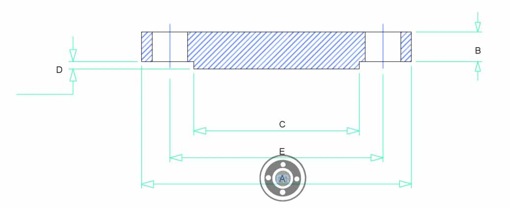
How to measure size?
To inspect the size and dimension of a blind flange, one needs to check the following things:
- They should consider the out diameter of the body.
- Also, check the bolt circle and the bolt hole diameter.
- It is crucial to have a look at the straightness and alignment of the bolt hole.
- And finally, the thickness of the blind should also be considered.
The dimensions are covered in ASME B16.5 for the size NPS ½” to NPS 24. It is covered in ASME B16.47 for the size above NPS 26" to NPS 60".
Uses & applications
The primary purpose of a blind flange is to terminate the end of a pipeline. This makes the maintenance of the pipeline easier. It also helps in sealing the nozzle opening in a pressure vessel.
What is the difference between a blank and a blind flange?
A blank flange can be described as a thin plate between pipe flanges in a pipeline to stop the flow. BLRF are thick, with or without bolt holes in the middle. It helps in controlling the flow through the pipe’s end.
Contact directly a Blind Flange manufacturers in India for lowest price, buy rf/ ff/ rtj face PN16 Blank Flange and Ductile Iron Blank Flange at Unbeatable Prices in Asia
Blind Flange Weight Chart
| NPS (Nominal Pipe Size) | NPT (Threaded) | WRNR (Weld Neck) | SWRF (Socket Weld) | Loose (Lap Joint) | SORF (Slip On) | BLRF (Blind) |
|---|---|---|---|---|---|---|
| ½ | 1 | 2 | 2 | 1 | 1 | 2 |
| ¾ | 2 | 2 | 2 | 2 | 2 | 2 |
| 1 | 2 | 3 | 2 | 2 | 2 | 2 |
| 1¼ | 3 | 3 | 3 | 3 | 3 | 3 |
| 1½ | 3 | 4 | 3 | 3 | 3 | 4 |
| 2 | 5 | 6 | 5 | 5 | 5 | 5 |
| 2½ | 8 | 10 | 8 | 8 | 8 | 7 |
| 3 | 9 | 11.5 | 9 | 9 | 9 | 9 |
| 3½ | 12 | 12 | 11 | 11 | 11 | 13 |
| 4 | 13 | 16.5 | 13 | 13 | 13 | 17 |
| 5 | 15 | 21 | 15 | 15 | 15 | 20 |
| 6 | 19 | 26 | 19 | 19 | 19 | 27 |
| 8 | 30 | 42 | 30 | 30 | 30 | 47 |
| 10 | 43 | 54 | 43 | 43 | 43 | 70 |
| 12 | 64 | 88 | 64 | 64 | 64 | 123 |
| 14 | 90 | 114 | 90 | 105 | 90 | 140 |
| 16 | 98 | 140 | 98 | 140 | 106 | 180 |
| 18 | 130 | 165 | 130 | 160 | 130 | 220 |
| 20 | 165 | 197 | 165 | 195 | 165 | 285 |
| 22 | 185 | 225 | 185 | 245 | 185 | 355 |
| 24 | 220 | 268 | 220 | 275 | 220 | 430 |
Blind Flange Types

Carbon Steel Blind Flange

Blind Flange A105

Mild Steel Raised Face Blind Flange

A105 Blind Flange

Ductile Iron Blind Flange

Alloy Steel Blind Flange

Aluminum Blank Flange

Stainless Steel 304 Blank Flange

SAE Blind Flange

12 Inch Blind Flange

PN16 Blank Flange

ASTM A182 F304 High Hub Blind Flange

Nickel Alloy High Hub Blind Flange

A182 F11 Reducing Blind Flange

Titanium Rf Blind Flange

Hastelloy Reducing Blind Flange

Ductile Iron Blank Flange

Gi Blind Flange

Alloy Steel Threaded Blind Flange

PN16 Blind Flange

Duplex Blank Flange

UNS S31803 Blind Flange With Threaded Hole

Cs Blind Flange

316 Stainless Steel Blind Flange

ASTM A182 F316 Raised Face Blind Flange

Super Duplex Threaded Blind Flange

SS 304 Blind Flange

2 Inch Blind Flange

316 SS Blind Flange

Copper Flat Face Blind Flange

ASTM A350 LF2 Flat Face Blind Flange

Inconel Blind Flange With Threaded Hole

ASTM A516 Gr.70 Rf Blind Flange
Stainless Steel Blind Flange Thickness Calculation
t = d *(CP/SE+1.9W hg/SE*d^3) ½
- d= Diameter or short span, measured as indicated in Fig. UG-34
- E= Joint efficiency, from Table UW-12, of any category A weld as defined in UG-3(a)
- S= Maximum allowable stress value in tension from applicable table of value
- W= Total bolt load
- hg= Gasket moment arm, equal to the radial distance from the centerline of the bolts to the line of the gasket reaction
- P = Design pressure-HYDROTEST pressure is considered (13.5 bar (g))
- C = 0.3 From Fig UG-34(j)
Stainless Steel Blind Flange Prices
| Stainless Steel Blind Flange Price Per Piece in India | Price Applicable for jan 2022 to june 2022 | Price Applicable for July 2022 to December 2022 |
| FLANGES STAINLESS STEEL GR 182 F304 VIAR SEAL RING BLIND Per Kg | US $501.21 | US $503.21 |
| FLANGES STAINLESS STEEL SA182 GR.F 304 BLIND CO-133,THK55MM Per Kg | US $9.25 | US $11.25 |
| STAINLESS STEEL FLANGES GRADE 304L - SIZE: 8 150 # BLIND RF Per Piece | US $66.87 | US $68.87 |
We are Blind Flange manufacturers in India. This is an approximate Cost of ASME B16.5 BLRF Flange in India. Compare our price with other PN16 Blank Flange manufacturer in India.
Supplier of 2 Inch/12 Inch SS 304 Blind Flange With Threaded Hole in Mumbai, manufacturer of Titanium Raised Face Blind Flange and ASTM A182 F316 High Hub Blind Flange offers hydrostatic testing to ensure tightness and strength
Carbon Steel Blind Flange Price List
| Carbon Steel Blind Flanges Price Per Piece in India | Carbon A105 BLRF Flanges Price in INR | CS Blank Flanges Price in UAE Dirham | ASTM A350 LF2 RF Blind Orifice Flanges Fitting Price in USD |
| CARBON STEEL FLANGES - BLIND, A105 RF, CL150, DN150 Per Kg | 152 | UAE Dirham 7.53 | $2.05 |
| Blind Flanges RF Class 600 2 Inch A105N Per Unit | 1,126 | UAE Dirham 55.79 | $15.19 |
| FLANGES 2 , 150# BLIND RD A105N Per Piece | 1,039 | UAE Dirham 51.48 | $14.01 |
Class 150 Blind Flange Dimensions
| Size in Inch |
Size in mm |
Outer Dia. |
Flanges Thick. |
RF Dia. |
RF Height |
PCD | No of Bolts |
Bolt Size UNC |
Machine Bolt Length |
RF Stud Length |
Hole Size | ISO Stud Size |
Weight in kg |
|---|---|---|---|---|---|---|---|---|---|---|---|---|---|
| A | B | C | D | E | |||||||||
| 1/2 | 15 | 90 | 9.6 | 34.9 | 2 | 60.3 | 4 | 1/2 | 50 | 55 | 5/8 | M14 | 0.9 |
| 3/4 | 20 | 100 | 11.2 | 42.9 | 2 | 69.9 | 4 | 1/2 | 50 | 65 | 5/8 | M14 | 0.9 |
| 1 | 25 | 110 | 12.7 | 50.8 | 2 | 79.4 | 4 | 1/2 | 55 | 65 | 5/8 | M14 | 0.9 |
| 1 1/4 | 32 | 115 | 14.3 | 63.5 | 2 | 88.9 | 4 | 1/2 | 55 | 70 | 5/8 | M14 | 1.4 |
| 1 1/2 | 40 | 125 | 15.9 | 73 | 2 | 98.4 | 4 | 1/2 | 65 | 70 | 5/8 | M14 | 1.8 |
| 2 | 50 | 150 | 17.5 | 92.1 | 2 | 120.7 | 4 | 5/8 | 70 | 85 | 3/4 | M16 | 2.3 |
| 2 1/2 | 65 | 180 | 20.7 | 104.8 | 2 | 139.7 | 4 | 5/8 | 75 | 90 | 3/4 | M16 | 3.2 |
| 3 | 80 | 190 | 22.3 | 127 | 2 | 152.4 | 4 | 5/8 | 75 | 90 | 3/4 | M16 | 4.1 |
| 3 1/2 | 90 | 215 | 22.3 | 139.7 | 2 | 177.8 | 8 | 5/8 | 75 | 90 | 3/4 | M16 | 5.9 |
| 4 | 100 | 230 | 22.3 | 157.2 | 2 | 190.5 | 8 | 5/8 | 75 | 90 | 3/4 | M16 | 7.7 |
| 5 | 125 | 255 | 22.3 | 185.7 | 2 | 215.9 | 8 | 3/4 | 85 | 95 | 7/8 | M20 | 9.1 |
| 6 | 150 | 280 | 23.9 | 215.9 | 2 | 241.3 | 8 | 3/4 | 85 | 100 | 7/8 | M20 | 11.8 |
| 8 | 200 | 345 | 27 | 269.9 | 2 | 298.5 | 8 | 3/4 | 90 | 110 | 7/8 | M20 | 20.5 |
| 10 | 250 | 405 | 28.6 | 323.8 | 2 | 362 | 12 | 7/8 | 100 | 115 | 1 | M24 | 32 |
| 12 | 300 | 485 | 30.2 | 381 | 2 | 431.8 | 12 | 7/8 | 100 | 120 | 1 | M24 | 50 |
| 14 | 350 | 535 | 33.4 | 412.8 | 2 | 476.3 | 12 | 1 | 115 | 135 | 1 1/8 | M27 | 64 |
| 16 | 400 | 595 | 35 | 469.9 | 2 | 539.8 | 16 | 1 | 115 | 135 | 1 1/8 | M27 | 82 |
| 18 | 450 | 635 | 38.1 | 533.4 | 2 | 577.9 | 16 | 1 1/8 | 125 | 145 | 1 1/4 | M30 | 100 |
| 20 | 500 | 700 | 41.3 | 584.2 | 2 | 635 | 20 | 1 1/8 | 140 | 160 | 1 1/4 | M30 | 130 |
| 24 | 600 | 815 | 46.1 | 692.2 | 2 | 749.3 | 20 | 1 1/4 | 150 | 170 | 1 3/8 | M33 | 196 |
300 Lb Blind Flange Dimensions
| Size in Inch |
Size in mm |
Outer Dia. |
Flanges Thick. |
RF Dia. |
RF Height |
PCD | No of Bolts |
Bolt Size UNC |
Machine Bolt Length |
RF Stud Length |
Hole Size |
ISO Stud Size |
Weight in kg |
|---|---|---|---|---|---|---|---|---|---|---|---|---|---|
| A | B | C | D | E | |||||||||
| 1/2 | 15 | 95 | 12.7 | 34.9 | 2 | 66.7 | 4 | 1/2 | 55 | 65 | 5/8 | M14 | 1.4 |
| 3/4 | 20 | 115 | 14.3 | 42.9 | 2 | 82.6 | 4 | 5/8 | 65 | 75 | 3/4 | M16 | 1.4 |
| 1 | 25 | 125 | 15.9 | 50.8 | 2 | 88.9 | 4 | 5/8 | 65 | 75 | 3/4 | M16 | 1.4 |
| 1 1/4 | 32 | 135 | 17.5 | 63.5 | 2 | 98.4 | 4 | 5/8 | 70 | 85 | 3/4 | M16 | 1.8 |
| 1 1/2 | 40 | 155 | 19.1 | 73 | 2 | 114.3 | 4 | 3/4 | 75 | 90 | 7/8 | M20 | 2.7 |
| 2 | 50 | 165 | 20.7 | 92.1 | 2 | 127 | 8 | 5/8 | 75 | 90 | 3/4 | M16 | 3.7 |
| 2 1/2 | 65 | 190 | 23.9 | 104.8 | 2 | 149.2 | 8 | 3/4 | 85 | 100 | 7/8 | M20 | 5.5 |
| 3 | 80 | 210 | 27 | 127 | 2 | 168.3 | 8 | 3/4 | 90 | 110 | 7/8 | M20 | 7.3 |
| 3 1/2 | 90 | 230 | 28.6 | 139.7 | 2 | 184.2 | 8 | 3/4 | 95 | 110 | 7/8 | M20 | 9.6 |
| 4 | 100 | 255 | 30.2 | 157.2 | 2 | 200 | 8 | 3/4 | 95 | 115 | 7/8 | M20 | 12.3 |
| 5 | 125 | 280 | 33.4 | 185.7 | 2 | 235 | 8 | 3/4 | 110 | 120 | 7/8 | M20 | 15.9 |
| 6 | 150 | 320 | 35 | 215.9 | 2 | 269.9 | 12 | 3/4 | 110 | 120 | 7/8 | M20 | 22.7 |
| 8 | 200 | 380 | 39.7 | 269.9 | 2 | 330.2 | 12 | 7/8 | 120 | 140 | 1 | M24 | 36 |
| 10 | 250 | 445 | 46.1 | 323.8 | 2 | 387.4 | 16 | 1 | 140 | 160 | 1 1/8 | M27 | 57 |
| 12 | 300 | 520 | 49.3 | 381 | 2 | 450.8 | 16 | 1 1/8 | 145 | 170 | 1 1/4 | M30 | 84 |
| 14 | 350 | 585 | 52.4 | 412.8 | 2 | 514.4 | 20 | 1 1/8 | 160 | 180 | 1 1/4 | M30 | 113 |
| 16 | 400 | 650 | 55.6 | 469.9 | 2 | 571.5 | 20 | 1 1/4 | 165 | 190 | 1 3/8 | M33 | 134 |
| 18 | 450 | 710 | 58.8 | 533.4 | 2 | 628.6 | 24 | 1 1/4 | 170 | 195 | 1 3/8 | M33 | 181 |
| 20 | 500 | 775 | 62 | 584.2 | 2 | 685.8 | 24 | 1 1/4 | 185 | 205 | 1 3/8 | M33 | 230 |
| 24 | 600 | 915 | 68.3 | 692.2 | 2 | 812.8 | 24 | 1 1/2 | 205 | 230 | 1 5/8 | M39 | 359 |
ASME B16.5 Class 600 Blind Flange Dimensions
| Size in Inch | Size in mm | Outer Dia. | Flanges Thick. | RF Dia. | RF Height | PCD | No of Bolts | Bolt Size UNC | RF Stud Length | Hole Size | ISO Stud Size | Weight in kg |
|---|---|---|---|---|---|---|---|---|---|---|---|---|
| A | B | C | D | E | ||||||||
| 1/2 | 15 | 95 | 14.3 | 34.9 | 7 | 66.7 | 4 | 1/2 | 75 | 5/8 | M14 | 1.4 |
| 3/4 | 20 | 115 | 15.9 | 42.9 | 7 | 82.6 | 4 | 5/8 | 90 | 3/4 | M16 | 1.4 |
| 1 | 25 | 125 | 17.5 | 50.8 | 7 | 88.9 | 4 | 5/8 | 90 | 3/4 | M16 | 1.8 |
| 1 1/4 | 32 | 135 | 20.7 | 63.5 | 7 | 98.4 | 4 | 5/8 | 95 | 3/4 | M16 | 2.3 |
| 1 1/2 | 40 | 155 | 22.3 | 73 | 7 | 114.3 | 4 | 3/4 | 110 | 7/8 | M20 | 3.7 |
| 2 | 50 | 165 | 25.4 | 92.1 | 7 | 127 | 8 | 5/8 | 110 | 3/4 | M16 | 4.6 |
| 2 1/2 | 65 | 190 | 28.6 | 104.8 | 7 | 149.2 | 8 | 3/4 | 120 | 7/8 | M20 | 6.8 |
| 3 | 80 | 210 | 31.8 | 127 | 7 | 168.3 | 8 | 3/4 | 125 | 7/8 | M20 | 9.1 |
| 3 1/2 | 90 | 230 | 35 | N/A | 7 | 184.2 | 8 | 7/8 | 140 | 1 | M24 | 13.2 |
| 4 | 100 | 275 | 38.1 | 157.2 | 7 | 215.9 | 8 | 7/8 | 145 | 1 | M24 | 18.7 |
| 5 | 125 | 330 | 44.5 | 185.7 | 7 | 266.7 | 8 | 1 | 165 | 1 1/8 | M27 | 31 |
| 6 | 150 | 355 | 47.7 | 215.9 | 7 | 292.1 | 12 | 1 | 170 | 1 1/8 | M27 | 39 |
| 8 | 200 | 420 | 55.6 | 269.9 | 7 | 349.2 | 12 | 1 1/8 | 190 | 1 1/4 | M30 | 64 |
| 10 | 250 | 510 | 63.5 | 323.8 | 7 | 431.8 | 16 | 1 1/4 | 215 | 1 3/8 | M33 | 105 |
| 12 | 300 | 560 | 66.7 | 381 | 7 | 489 | 20 | 1 1/4 | 220 | 1 3/8 | M33 | 134 |
| 14 | 350 | 605 | 69.9 | 412.8 | 7 | 527 | 20 | 1 3/8 | 235 | 1 1/2 | M36 | 161 |
| 16 | 400 | 685 | 76.2 | 469.9 | 7 | 603.2 | 20 | 1 1/2 | 255 | 1 5/8 | M39 | 225 |
| 18 | 450 | 745 | 82.6 | 533.4 | 7 | 654 | 20 | 1 5/8 | 275 | 1 3/4 | M42 | 286 |
| 20 | 500 | 815 | 88.9 | 584.2 | 7 | 723.9 | 24 | 1 5/8 | 285 | 1 3/4 | M42 | 368 |
| 24 | 600 | 940 | 101.6 | 692.2 | 7 | 838.2 | 24 | 1 7/8 | 330 | 2 | M48 | 568 |
Check large diameter Mild Steel SAE Blind Flange and Nickel Alloy Forged Blind Flange torque chart & price in India, manufacturing various types including High Hub, Tapped, Threaded Blind Flange, check PN16 ASTM A182 F304 Blank Flange dimensions
Class 900 Blind Flanges Dimensions
| Size in Inch | Size in mm | Outer Dia. | Flanges Thick. | RF Dia. | RF Height | PCD | No of Bolts | Bolt Size UNC | RF Stud Length | Hole Size | ISO Stud Size | Weight in kg |
|---|---|---|---|---|---|---|---|---|---|---|---|---|
| A | B | C | D | E | ||||||||
| 1/2 | 15 | 120 | 22.3 | 34.9 | 7 | 82.6 | 4 | 3/4 | 110 | 7/8 | M20 | 1.8 |
| 3/4 | 20 | 130 | 25.4 | 42.9 | 7 | 88.9 | 4 | 3/4 | 115 | 7/8 | M20 | 2.7 |
| 1 | 25 | 150 | 28.6 | 50.8 | 7 | 101.6 | 4 | 7/8 | 125 | 1 | M24 | 3.6 |
| 1 1/4 | 32 | 160 | 28.6 | 63.5 | 7 | 111.1 | 4 | 7/8 | 125 | 1 | M24 | 4.1 |
| 1 1/2 | 40 | 180 | 31.8 | 73 | 7 | 123.8 | 4 | 1 | 140 | 1 1/8 | M27 | 5.9 |
| 2 | 50 | 215 | 38.1 | 92.1 | 7 | 165.1 | 8 | 7/8 | 145 | 1 | M24 | 10.1 |
| 2 1/2 | 65 | 245 | 41.3 | 104.8 | 7 | 190.5 | 8 | 1 | 160 | 1 1/8 | M27 | 16 |
| 3 | 80 | 240 | 38.1 | 127 | 7 | 190.5 | 8 | 7/8 | 145 | 1 | M24 | 13 |
| 4 | 100 | 290 | 44.5 | 157.2 | 7 | 235 | 8 | 1 1/8 | 170 | 1 1/4 | M30 | 24.5 |
| 5 | 125 | 350 | 50.8 | 185.7 | 7 | 279.4 | 8 | 1 1/4 | 190 | 1 3/8 | M33 | 39.5 |
| 6 | 150 | 380 | 55.6 | 215.9 | 7 | 317.5 | 12 | 1 1/8 | 190 | 1 1/4 | M30 | 53 |
| 8 | 200 | 470 | 63.5 | 269.9 | 7 | 393.7 | 12 | 1 3/8 | 220 | 1 1/2 | M36 | 91 |
| 10 | 250 | 545 | 69.9 | 323.8 | 7 | 469.9 | 16 | 1 3/8 | 235 | 1 1/2 | M36 | 132 |
| 12 | 300 | 610 | 79.4 | 381 | 7 | 533.4 | 20 | 1 3/8 | 255 | 1 1/2 | M36 | 189 |
| 14 | 350 | 640 | 85.8 | 412.8 | 7 | 558.8 | 20 | 1 1/2 | 275 | 1 5/8 | M39 | 237 |
| 16 | 400 | 705 | 88.9 | 469.9 | 7 | 616 | 20 | 1 5/8 | 285 | 1 3/4 | M42 | 273 |
| 18 | 450 | 785 | 101.6 | 533.4 | 7 | 685.8 | 20 | 1 7/8 | 325 | 2 | M48 | 367 |
| 20 | 500 | 855 | 108 | 584.2 | 7 | 749.3 | 20 | 2 | 350 | 2 1/8 | M52 | 463 |
| 24 | 600 | 1040 | 139.7 | 692.2 | 7 | 901.7 | 20 | 2 1/2 | 440 | 2 5/8 | M64 | 875 |
1500 Lb Blind Flange Dimensions
| Size in Inch | Size in mm | Outer Dia. | Flanges Thick. | RF Dia. | RF Height | PCD | No of Bolts | Bolt Size UNC | RF Stud Length | Hole Size | ISO Stud Size | Weight in kg |
|---|---|---|---|---|---|---|---|---|---|---|---|---|
| A | B | C | D | E | ||||||||
| 1/2 | 15 | 120 | 22.3 | 34.9 | 7 | 82.6 | 4 | 3/4 | 110 | 7/8 | M20 | 1.8 |
| 3/4 | 20 | 130 | 25.4 | 42.9 | 7 | 88.9 | 4 | 3/4 | 115 | 7/8 | M20 | 2.7 |
| 1 | 25 | 150 | 28.6 | 50.8 | 7 | 101.6 | 4 | 7/8 | 125 | 1 | M24 | 3.7 |
| 1 1/4 | 32 | 160 | 28.6 | 63.5 | 7 | 111.1 | 4 | 7/8 | 125 | 1 | M24 | 4.1 |
| 1 1/2 | 40 | 180 | 31.8 | 73 | 7 | 123.8 | 4 | 1 | 140 | 1 1/8 | M27 | 5.9 |
| 2 | 50 | 215 | 38.1 | 92.1 | 7 | 165.1 | 8 | 7/8 | 145 | 1 | M24 | 10.1 |
| 2 1/2 | 65 | 245 | 41.3 | 104.8 | 7 | 190.5 | 8 | 1 | 160 | 1 1/8 | M27 | 15.9 |
| 3 | 80 | 265 | 47.7 | 127 | 7 | 203.2 | 8 | 1 1/8 | 180 | 1 1/4 | M30 | 21.8 |
| 4 | 100 | 310 | 54 | 157.2 | 7 | 241.3 | 8 | 1 1/4 | 195 | 1 3/8 | M33 | 33 |
| 5 | 125 | 375 | 73.1 | 185.7 | 7 | 292.1 | 8 | 1 1/2 | 250 | 1 5/8 | M39 | 64 |
| 6 | 150 | 395 | 82.6 | 215.9 | 7 | 317.5 | 12 | 1 3/8 | 260 | 1 1/2 | M36 | 75 |
| 8 | 200 | 485 | 92.1 | 269.9 | 7 | 393.7 | 12 | 1 5/8 | 290 | 1 3/4 | M42 | 136 |
| 10 | 250 | 585 | 108 | 323.8 | 7 | 482.6 | 12 | 1 7/8 | 335 | 2 | M48 | 232 |
| 12 | 300 | 675 | 123.9 | 381 | 7 | 571.5 | 16 | 2 | 375 | 2 1/8 | M52 | 314 |
| 14 | 350 | 750 | 133.4 | 412.8 | 7 | 635 | 16 | 2 1/4 | 405 | 2 3/8 | M56 | 443 |
| 16 | 400 | 825 | 146.1 | 469.9 | 7 | 704.8 | 16 | 2 1/2 | 445 | 2 5/8 | M64 | 591 |
| 18 | 450 | 915 | 162 | 533.4 | 7 | 774.7 | 16 | 2 3/4 | 495 | 2 7/8 | M72 | 795 |
| 20 | 500 | 985 | 177.8 | 584.2 | 7 | 831.8 | 16 | 3 | 540 | 3 1/8 | M76 | 1022 |
| 24 | 600 | 1170 | 203.2 | 692.2 | 7 | 990.6 | 16 | 3 1/2 | 615 | 3 5/8 | M90 | 1648 |
Class 2500 Blind Flange Dimensions
| Size in Inch | Size in mm | Outer Dia. | Flanges Thick. | RF Dia. | RF Height | PCD | No of Bolts | Bolt Size UNC | RF Stud Length | Hole Size | ISO Stud Size | Weight in kg |
|---|---|---|---|---|---|---|---|---|---|---|---|---|
| A | B | C | D | E | ||||||||
| 1/2 | 15 | 135 | 30.2 | 34.9 | 7 | 88.9 | 4 | 3/4 | 120 | 7/8 | M20 | 3.2 |
| 3/4 | 20 | 140 | 31.8 | 42.9 | 7 | 95.2 | 4 | 3/4 | 125 | 7/8 | M20 | 3.7 |
| 1 | 25 | 160 | 35 | 50.8 | 7 | 108 | 4 | 7/8 | 140 | 1 | M24 | 5 |
| 1 1/4 | 32 | 185 | 38.1 | 63.5 | 7 | 130.2 | 4 | 1 | 150 | 1 1/8 | M27 | 7.8 |
| 1 1/2 | 40 | 205 | 44.5 | 73 | 7 | 146 | 4 | 1 1/8 | 170 | 1 1/4 | M30 | 10.5 |
| 2 | 50 | 235 | 50.9 | 92.1 | 7 | 171.4 | 8 | 1 | 180 | 1 1/8 | M27 | 18 |
| 2 1/2 | 65 | 265 | 57.2 | 104.8 | 7 | 196.8 | 8 | 1 1/8 | 195 | 1 1/4 | M30 | 25.5 |
| 3 | 80 | 305 | 66.7 | 127 | 7 | 228.6 | 8 | 1 1/4 | 220 | 1 3/8 | M33 | 39 |
| 4 | 100 | 355 | 76.2 | 157.2 | 7 | 273 | 8 | 1 1/2 | 255 | 1 5/8 | M39 | 61.5 |
| 5 | 125 | 420 | 92.1 | 185.7 | 7 | 323.8 | 8 | 1 3/4 | 300 | 1 7/8 | M45 | 102 |
| 6 | 150 | 485 | 108 | 215.9 | 7 | 368.3 | 8 | 2 | 345 | 2 1/8 | M52 | 157 |
| 8 | 200 | 550 | 127 | 269.9 | 7 | 438.2 | 12 | 2 | 380 | 2 1/8 | M52 | 241 |
| 10 | 250 | 675 | 165.1 | 323.8 | 7 | 539.8 | 12 | 2 1/2 | 490 | 2 5/8 | M64 | 470 |
| 12 | 300 | 760 | 184.2 | 381 | 7 | 619.1 | 12 | 2 3/4 | 540 | 2 7/8 | M72 | 575 |
Manufacturer of ASTM A707 Grade L5 Blank Flange and Alloy Steel ASTM A694 F42 blind flange for hydrotest, manufactring Raised Flat Face & Rf Blind Flange in various matals including Copper, Aluminum, Nickel, Brass, Monel, Inconel, Alloy 20, 254 SMO, and Hastelloy
Blind Flange Hs Code
| HS Code | 73072100 |
SAE Blind Flange Dimensions

Pn16 Blank Flange Dimensions
| DIN 2527 PN16 BLIND FLANGES | |||||||
| Rated Diameter |
Flanges | Screws | Weight (7,85 Kg/dm3) |
||||
| D | b | k | Number | Thread | d2 | Shape B | |
| Kg | |||||||
| 15 | 95 | 14 | 65 | 4 | M 12 | 14 | 0,72 |
| 20 | 105 | 16 | 75 | 1,01 | |||
| 25 | 115 | 16 | 85 | 1,23 | |||
| 32 | 140 | 16 | 100 | M 16 | 18 | 1,8 | |
| 40 | 150 | 16 | 110 | 2,09 | |||
| 50 | 165 | 18 | 125 | 2,88 | |||
| 65 | 185 | 18 | 145 | 3,66 | |||
| 80 | 200 | 20 | 160 | 8 | 4,77 | ||
| 100 | 220 | 20 | 180 | 5,65 | |||
| 125 | 250 | 22 | 210 | 8,42 | |||
| 150 | 285 | 22 | 240 | M 20 | 22 | 10,4 | |
| 200 | 340 | 24 | 295 | 12 | 16,1 | ||
| 250 | 405 | 26 | 355 | M 24 | 26 | 24,9 | |
| 300 | 460 | 28 | 410 | 35,1 | |||
| 350 | 520 | 30 | 470 | 16 | 47,8 | ||
| 400 | 580 | 32 | 525 | M 27 | 30 | 63,5 | |
| 500 | 715 | 36 | 650 | 20 | M 30 | 33 | 102 |
Stainless Steel Blind Flange Pcd Chart
| ANSI 150# | ||||
| Pipe NB | Bolt PCD | No. of Bolts | Bolt Size | Flanges OD |
| 1/2" | 2 3/8" | 4 | 1/2" | 3 1/2" |
| 1" | 3 1/8" | 4 | 1/2" | 4 1/4" |
| 2" | 4 3/4" | 4 | 5/8" | 6" |
| 4" | 7 1/2" | 8 | 5/8" | 9" |
| 6" | 9 1/2" | 8 | 3/4" | 11" |
| 8" | 11 3/4" | 8 | 3/4" | 13 1/2" |
| 10" | 14 1/4" | 12 | 7/8" | 16" |
| 12" | 17 " | 12 | 7/8" | 19" |
| 14" | 18 3/4" | 12 | 1" | 21" |
Blind Flange Pressure Rating
|
Temp
-29 °C |
150
|
300
|
400
|
600
|
900
|
1500
|
2500
|
|
50
|
19.2
|
50.1
|
66.8
|
100.2
|
150.4
|
250.6
|
417.7
|
|
38
|
19.6
|
51.1
|
68.1
|
102.1
|
153.2
|
255.3
|
425.5
|
|
150
|
15.8
|
45.1
|
60.1
|
90.2
|
135.2
|
225.4
|
375.6
|
|
100
|
17.7
|
46.6
|
62.1
|
93.2
|
139.8
|
233
|
388.3
|
|
250
|
12.1
|
41.9
|
55.9
|
83.9
|
125.8
|
209.7
|
349.5
|
|
200
|
13.8
|
43.8
|
58.4
|
87.6
|
131.4
|
219
|
365
|
|
300
|
10.2
|
39.8
|
53.1
|
79.6
|
119.5
|
199.1
|
331.8
|
|
350
|
8.4
|
37.6
|
50.1
|
75.1
|
112.7
|
187.8
|
313
|
|
325
|
9.3
|
38.7
|
51.6
|
77.4
|
116.1
|
193.6
|
322.6
|
|
375
|
7.4
|
36.4
|
48.5
|
72.7
|
109.1
|
181.8
|
303.1
|
|
425
|
5.5
|
28.8
|
38.4
|
57.5
|
86.3
|
143.8
|
239.7
|
|
400
|
6.5
|
34.7
|
46.3
|
69.4
|
104.2
|
173.6
|
289.3
|
|
450
|
4.6
|
23
|
30.7
|
46
|
69
|
115
|
191.7
|
|
500
|
2.8
|
11.8
|
15.7
|
23.5
|
35.3
|
58.8
|
97.9
|
|
475
|
3.7
|
17.4
|
23.2
|
34.9
|
52.3
|
87.2
|
145.3
|
|
538
|
1.4
|
5.9
|
7.9
|
11.8
|
17.7
|
29.5
|
49.2
|
Applications of Blind Flanges
- Refineries
- Nuclear Power
- Marine Applications
- Paper & Pulp
- Power Plants
- Fossil Fuel Power Plants
- Ship Building
- Oil And Gas Industry
Tolerances Of Flat Face Blind Flange
| Outside Diameter ≤ 24 = 1.6 mm | > 24 = ± 3.2 mm | Inside Diameter not applicable |
| Diameter of Contact Face 1.6 mm Raised Face = ± 0.8 mm6.35 mm Raised Face, Tongue & Groove / Male-Female = ± 0.4 mm | Outside Diameter of Hub ≤ 12 = + 2.4 mm / – 1.6 mm | ≥ 14 = ± 3.2 mm |
| Diameter of Counterbore not applicable | Drilling Bolt Circle = 1.6 mm | Bolt Hole Spacing = ± 0.8 mmEccentricity of Bolt Circle with Respect to Facing≤ 2½ = 0.8 mm max. | ≥ 3 = 1.6 mm max. |
| Thickness ≤ 18 = + 3.2 mm / – 0 | ≥ 20 = + 4.8 mm / – 0 | Length thru Hub ≤ 18 = + 3.2 mm / – 0.8 mm | ≥ 20 = + 4.8 mm / – 1.6 mm |
Flanges Types
Pipe Fittings Material
Flanges Material
Other Products