
- Call : +91 22 67436442
- exports@petrometflange.com
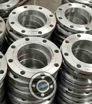
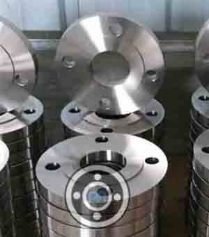
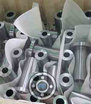
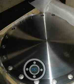
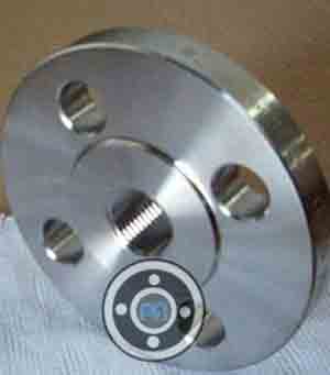
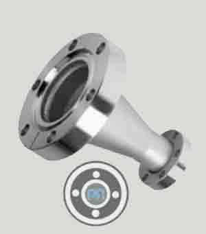
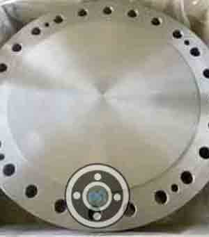
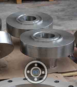
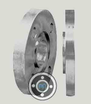
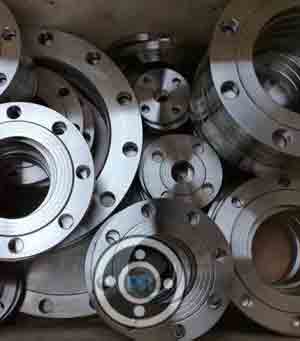
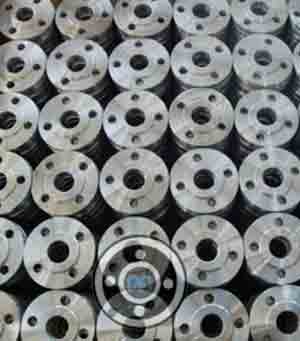
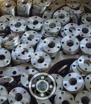
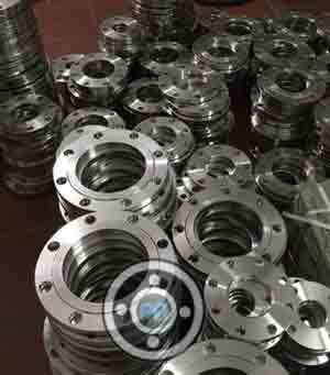
Monel 400 Flanges
- Home /
- Monel 400 Flanges
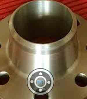
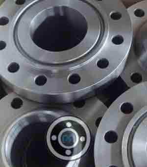
Alloy 400 Weld Neck Flanges & ASTM B564 UNS N04400 Blind Flange manufacturer in India
What is Monel 400 Flanges?
The Monel 400 material is a solid-solution alloy which can only be hardened by cold working. The Monel 400 flanges are widely used for heat exchangers and heaters. They are joined to the piping system using the most conventional welding methods. These flanges are used in a wide range of applications like valves and piping systems for marine equipment.
The Monel 400 flanges are known for their properties like corrosion resistance and high strength. Apart from general corrosion, they can also perform well in a wide range of acidic and alkaline environments. They possess high machinability and are available in a wide range of surface finishes according to specific requirements. The Monel 400 flanges have a slight magnetic property in room and it can even maintain its strength in the sub-zero temperature. The monel 400 material is known for giving a superior performance in a wide range of acidic and alkaline environments as well as saline water.
The monel 400 are known to possess high ductility and they have good thermal conductivity. One of the best things about this material is that it is able to retain its performance from sub-zero to a high temperature of 583 degrees C. There are different types of monel flanges available and they serve different purposes. Their dimensions can be customized according to the specifications given. They are made following the UNS N04400 and ASME SB-564 specifications. Apart from resisting general corrosion, the monel 400 flanges can also resist stress corrosion cracking. They are high in toughness and are a popular choice for various unique applications. The alloy contains elements like nickel, silicon, manganese, iron, carbon, sulfur, and copper. Monel 400 flanges maintain a high quality and they are safe to use. They can work efficiently in a wide range of temperatures and hence are used in various services.
Alloy 400 Blind Flanges Vs ASTM B564 UNS N04400 Slip on Flange
The main point of difference between Alloy 400 Blind Flanges and ASTM B564 UNS N04400 Slip on Flange is in their structure. While the blind flange looks like a steel plate with bolted holes all around it and no central hub, the slip on flange looks like a ring that can be slid into the pipe. The blind flange is joined to the piping system by bolting it while the slip on flange is first inserted to the pipe, and then double welded from inside and outside. The blind flanges are used for stopping the flow connection or sealing the nozzle of the vessel, whereas the slip on flanges are primarily used in low pressure piping systems, where there is a less risk of leakage. Being made of the same material, both the flanges are used in similar environments and industries, like the marine applications.
Monel 400 Flanges vs Monel 500 Flanges
The Monel 400 material is a nickel-copper alloy that can only be hardened by cold working. It has high toughness and strength through a wide range of temperatures. The monel 400 flanges are known for performing well in corrosive environments. They are typically used in pumps and valves, across industries like marine and chemical processing. It is resistant to attacks by several acids and alkalis.
On the other hand, the monel 500 material is a copper-nickel alloy which is age-hardened. It has good corrosion resistance properties, along with erosion resistance and also high strength fatigue. The alloy consists of titanium and aluminium in its composition and it is precipitated hardened. It possesses higher strength and hardness compared to the monel 400. It has around double the tensile strength and triple the yield strength of the 400 flange.
Why is Nickel 400 Flanges so expensive?
The Nickel 400 Flanges are so expensive because of its chemical composition. Also the characteristics and critical applications where they are used increases the demand of these flanges, making them so expensive.
Unlike the Monel 400, the Monel 500 material has titanium in it. The 500 alloy has lower coefficient of friction and they also have higher wear resistance compared to any other Monel alloys. It’s mechanical properties like strength and hardness are also superior compared to the Monel 400 material. However, Monel 400 material contains at least 62% of the nickel metal, which is quite expensive and its unique characteristics cannot be substituted by any other element that is cheaper. Thus, the demand remains high, and also the cost of making the Monel 400 flange and hence they are so expensive.

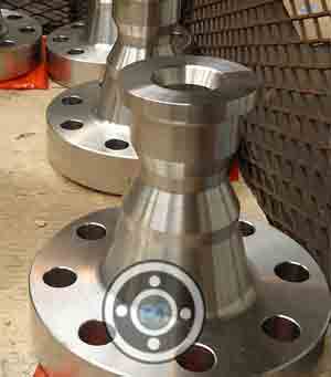
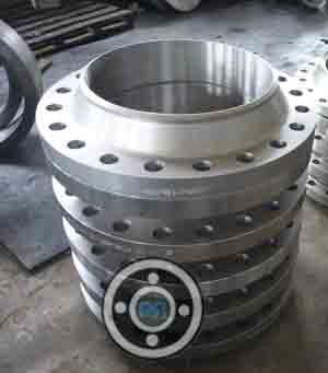
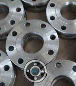
Monel 400 Flanges
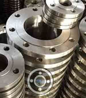
KNPC approved API 605 Alloy 400 Slip On Flange manufacturers in India offers widest selection of AWWA C207 ASME SB564 N04400 Threaded Flange and Monel 400 Long Weld Neck Flange Material in Mumbai
Table of Content
- Monel 400 Flanges Specification List
- Monel Flange Pressure Rating
- Nickel 400 Flange Dimensions
- Monel Flanges Price
- Dimension Table of Monel 400 Weld Neck Flanges
- Class 150 Monel 400 Flange Dimensions
- Class 900 Alloy 400 Flange Dimension Table
- Weight Chart of Monel 400 Flange
- Monel 400 Pipe Flanges Chemical Composition
- Alloy 400 Flanges Mechanical Properties
- Monel Alloy 400 Flanges Equivalent Grade
- Physical Properties of Monel Flange
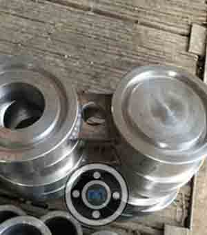
- Different Types of Monel 400 Flanges
- Dimensional Tolerance of ASTM B564 UNS N04400 Flanges
- What are the characteristics of Monel 400 Slip on Flanges?
- Monel 400 Pipe Flanges Fabrication
- Nickel Alloy 400 Flange Density & Melting point
- In what applications is ASTM B564 Alloy 400 Flanges used?
Monel 400 Flanges Specification List
| Size Range | 1/2″ to 48″ |
|---|---|
| Chart of Pressure Rating | 300 LBS, 2500 LBS, 1500 LBS, 900 LBS, 150 LBS, 600 LBS |
| DIN Pressure Calculation | 25Bar 40Bar 16Bar 6Bar 10Bar / PN64 PN10 PN25 PN16 PN6 PN40 |
| JIS | 40 K, 16 K, 5K, 10 K, 30 K, 20 K, 63 K |
| Manufacturer of Connect / Flange Face Type | LJF, RF, RTJ, FF, Small Tongue, Large Tongue & Groove |
| Manufacturer of | GOST, JIS, ANSI, DIN, UNI, BS, AWWA, AS2129, SABS, NFE, EN etc. |
| Equipment | Pushing Machine, Press machine, Sand-blasting machine, Bending machine, electric bevelling machine etc |
| Test | Magnetic particle detector, X-ray detector, Ultrasonic flaw detector, Direct-reading Spectrograph, Hydrostatic testing machine |
| UNI / EN | 16Bar 6Bar 40Bar 10Bar 25Bar |
| Origin | Japan / West Europe / Indian / USA / Korean |
| Common Types By Manufacturer | Threaded / Screwed / Forged / Plate |
| Standards Provided By Manufacturer | ISO70051, MSS S44, BS1560-3.1, API7S-43, B16.48, ANSI/ASME B16.5, B16.47 Series A & B, BS4504, JISB2220, ASME/ANSI B16.5/16.36/16.47A/16.47B, API605, BS 10, EN-1092, DIN, API7S-15, EN1092 |
| Production technique Used By Manufacturer | Heat treated, Forged and machined |
| Coating | Zinc Plated, Anti-rust Paint, Yellow Transparent, Oil Black Paint, Cold and Hot Dip Galvanized |
Are you looking for Monel 400 Pipe Flanges stockists, distributor, dealers, supplier, wholesalers, importer, stockholders, exporters and Manufacturer in Mumbai.
Monel Flange Pressure Rating
| Temperature °F | Class 150 | Class 600 | Class 1500 | Class 400 | Class 900 | Class 300 | Class 2500 |
| -20 to 100 | 275 | 1440 | 3600 | 960 | 2160 | 720 | 6000 |
| 300 | 205 | 1080 | 2700 | 720 | 1620 | 540 | 4500 |
| 200 | 230 | 1200 | 3000 | 800 | 1800 | 600 | 5000 |
| 400 | 190 | 995 | 2485 | 660 | 1490 | 495 | 4140 |
| 600 | 140 | 875 | 2185 | 580 | 1310 | 435 | 3640 |
| 650 | 125 | 860 | 2150 | 575 | 1290 | 430 | 3580 |
| 500 | 170 | 930 | 2330 | 620 | 1395 | 465 | 3880 |
| 700 | 110 | 850 | 2125 | 565 | 1275 | 425 | 3540 |
| 750 | 95 | 830 | 2075 | 555 | 1245 | 415 | 3460 |
| 850 | 65 | 790 | 1980 | 530 | 1190 | 395 | 3300 |
| 800 | 80 | 805 | 2015 | 540 | 1210 | 405 | 3360 |
| 900 | 50 | 780 | 1945 | 520 | 1165 | 390 | 3240 |
| 950 | 35 | 765 | 1910 | 510 | 1145 | 380 | 3180 |
| 1000 | 20 | 640 | 1605 | 430 | 965 | 320 | 2675 |
| 1100 | 20 | 515 | 1285 | 345 | 770 | 255 | 2145 |
| 1150 | 20 | 400 | 995 | 265 | 595 | 200 | 1655 |
| 1050 | 20 | 615 | 1545 | 410 | 925 | 310 | 2570 |
| 1200 | 20 | 310 | 770 | 205 | 465 | 155 | 1285 |
| 1250 | 20 | 225 | 565 | 150 | 340 | 115 | 945 |
| 1300 | 20 | 170 | 430 | 115 | 255 | 85 | 715 |
| 1400 | 20 | 95 | 240 | 65 | 145 | 50 | 400 |
| 1350 | 20 | 125 | 310 | 80 | 185 | 60 | 515 |
| 1450 | 15 | 70 | 170 | 45 | 105 | 35 | 285 |
| 1500 | 10 | 55 | 135 | 35 | 80 | 25 | 230 |
Nickel 400 Flange Dimensions
| Size in Inch | RF Dia. | Size in mm | Machine Bolt Length | Flange Thickness | ISO Stud Size | PCD | No of Bolts | Bolt Size UNC | Outer Dia. | RF Height | RF Stud Length | Hole Size | Weight in kg |
| C | B | E | A | D | |||||||||
| 1/2 | 34.9 | 15 | 50 | 9.6 | M14 | 60.3 | 4 | 1/2 | 90 | 2 | 55 | 5/8 | 0.9 |
| 1 | 50.8 | 25 | 55 | 12.7 | M14 | 79.4 | 4 | 1/2 | 110 | 2 | 65 | 5/8 | 0.9 |
| 1 1/4 | 63.5 | 32 | 55 | 14.3 | M14 | 88.9 | 4 | 1/2 | 115 | 2 | 70 | 5/8 | 1.4 |
| 3/4 | 42.9 | 20 | 50 | 11.2 | M14 | 69.9 | 4 | 1/2 | 100 | 2 | 65 | 5/8 | 0.9 |
| 1 1/2 | 73 | 40 | 65 | 15.9 | M14 | 98.4 | 4 | 1/2 | 125 | 2 | 70 | 5/8 | 1.8 |
| 2 | 92.1 | 50 | 70 | 17.5 | M16 | 120.7 | 4 | 5/8 | 150 | 2 | 85 | 3/4 | 2.3 |
| 3 | 127 | 80 | 75 | 22.3 | M16 | 152.4 | 4 | 5/8 | 190 | 2 | 90 | 3/4 | 4.1 |
| 3 1/2 | 139.7 | 90 | 75 | 22.3 | M16 | 177.8 | 8 | 5/8 | 215 | 2 | 90 | 3/4 | 5.9 |
| 4 | 157.2 | 100 | 75 | 22.3 | M16 | 190.5 | 8 | 5/8 | 230 | 2 | 90 | 3/4 | 7.7 |
| 5 | 185.7 | 125 | 85 | 22.3 | M20 | 215.9 | 8 | 3/4 | 255 | 2 | 95 | 7/8 | 9.1 |
| 2 1/2 | 104.8 | 65 | 75 | 20.7 | M16 | 139.7 | 4 | 5/8 | 180 | 2 | 90 | 3/4 | 3.2 |
| 6 | 215.9 | 150 | 85 | 23.9 | M20 | 241.3 | 8 | 3/4 | 280 | 2 | 100 | 7/8 | 11.8 |
| 8 | 269.9 | 200 | 90 | 27 | M20 | 298.5 | 8 | 3/4 | 345 | 2 | 110 | 7/8 | 20.5 |
| 10 | 323.8 | 250 | 100 | 28.6 | M24 | 362 | 12 | 7/8 | 405 | 2 | 115 | 1 | 32 |
| 12 | 381 | 300 | 100 | 30.2 | M24 | 431.8 | 12 | 7/8 | 485 | 2 | 120 | 1 | 50 |
| 14 | 412.8 | 350 | 115 | 33.4 | M27 | 476.3 | 12 | 1 | 535 | 2 | 135 | 1 1/8 | 64 |
| 16 | 469.9 | 400 | 115 | 35 | M27 | 539.8 | 16 | 1 | 595 | 2 | 135 | 1 1/8 | 82 |
| 18 | 533.4 | 450 | 125 | 38.1 | M30 | 577.9 | 16 | 1 1/8 | 635 | 2 | 145 | 1 1/4 | 100 |
| 20 | 584.2 | 500 | 140 | 41.3 | M30 | 635 | 20 | 1 1/8 | 700 | 2 | 160 | 1 1/4 | 130 |
| 24 | 692.2 | 600 | 150 | 46.1 | M33 | 749.3 | 20 | 1 1/4 | 815 | 2 | 170 | 1 3/8 | 196 |
Supplier of EN 1092-2 400 Monel Socket Weld Flange and ASME B16.5 Nickel Alloy 400 Spectacle Blinds offers Pneumatic, Hydrotest, NDT Test to confirm the integrity of weldments
Monel Flanges Price
| Monel 400 Flanges Price Per Piece in India | Alloy 400 Pipe Flanges Price in INR | Nickel 400 Flanges Price in UAE Dirham | Monel Alloy 400 Flange Price in USD |
| FLANGS-MONEL400 3/4 WN 1500 RF XS/80S Per Kg | 3,819 | UAE Dirham 184.52 | $50.24 |
| FLANGES - MONEL400 3/4 WN 1500 RF XS/80S 125-250 RMS Per Kg | 5,501 | UAE Dirham 265.79 | $72.36 |
| FLANGES-MONEL400 1/2 WIN 1500 RF SCH 80S Per Piece | 9,400 | UAE Dirham 454.15 | $123.65 |
Compare our prices to those of other Monel 400 Flanges manufacturers in India before making a purchase. This is an approximation of the ASTM B564 UNS N04400 Flanges pricing in India. For the most up-to-date stocklist of Monel Flanges in Mumbai, please contact us.
Dimension Table of Monel 400 Weld Neck Flanges

| Flange NPS | H | Inside Diameter |
Flat Face Thickness (T2) |
Outside Diameter |
Raised Face (RF) |
Raised Face (R) |
H1 | Raised Face Thickness (T) |
T1 | Bolt Circle (BC) |
Bolt Hole (B) |
No. of Bolt Holes |
|---|---|---|---|---|---|---|---|---|---|---|---|---|
| 1/2" | 1.19" | 0.62" | 1.82" | 3.50" | .063" | 1.38" | 0.84" | 1.88" | .38" | 2.38" | .62" | 4 |
| 1-1/4" | 2.31" | 1.38" | 2.19" | 4.62" | .063" | 2.50" | 1.66" | 2.25" | .56" | 3.50" | .62" | 4 |
| 3/4" | 1.50" | 0.82" | 2.00" | 3.88" | .063" | 1.69" | 1.05" | 2.06" | .44" | 2.75" | .62" | 4 |
| 1-1/2" | 2.56" | 1.61" | 2.38" | 5.00" | .063" | 2.88" | 1.90" | 2.44" | .62" | 3.88" | .62" | 4 |
| 1" | 1.94" | 1.05" | 2.13" | 4.25" | .063" | 2.00" | 1.32" | 2.19" | .50" | 3.12" | .62" | 4 |
| 2" | 3.06" | 2.07" | 2.44" | 6.00" | .063" | 3.62" | 2.38" | 2.50" | .69" | 4.75" | .75" | 4 |
| 2-1/2" | 3.56" | 2.47" | 2.69" | 7.00" | .063" | 4.12" | 2.88" | 2.75" | .82" | 5.50" | .75" | 4 |
| 3" | 4.25" | 3.07" | 2.69" | 7.50" | .063" | 5.00" | 3.50" | 2.75" | .88" | 6.00" | .75" | 4 |
| 4" | 5.31" | 4.03" | 2.94" | 9.00" | .063" | 6.19" | 4.50" | 3.00" | .88" | 7.50" | .75" | 8 |
| 5" | 6.44" | 5.05" | 3.44" | 10.00" | .063" | 7.31" | 5.56" | 3.50" | .88" | 8.50" | .88" | 8 |
| 3-1/2" | 4.81" | 3.55" | 2.75" | 8.50" | .063" | 5.50" | 4.00" | 2.81" | .88" | 7.00" | .75" | 8 |
| 6" | 7.56" | 6.07" | 3.44" | 11.00" | .063" | 8.50" | 6.63" | 3.50" | .94" | 9.50" | .88" | 8 |
| 8" | 9.69" | 7.98" | 3.94" | 13.50" | .063" | 10.62" | 8.63" | 4.00" | 1.06" | 11.75" | .88" | 8 |
| 22" | 24.25" | 21.25" | 5.82" | 29.50" | .063" | 25.25" | 22.00" | 5.88" | 1.75" | 27.25" | 1.38" | 20 |
| 10" | 12.00" | 10.02" | 3.94" | 16.00" | .063" | 12.75" | 10.75" | 4.00" | 1.13" | 14.25" | 1.00" | 12 |
| 12" | 14.38" | 12.00" | 4.44" | 19.00" | .063" | 15.00" | 12.75" | 4.50" | 1.19" | 17.00" | 1.00" | 12 |
| 16" | 18.00" | 15.25" | 4.94" | 23.50" | .063" | 18.50" | 16.00" | 5.00" | 1.38" | 21.25" | 1.12" | 16 |
| 18" | 19.88" | 17.25" | 5.44" | 25.00" | .063" | 21.00" | 18.00" | 5.50" | 1.50" | 22.75" | 1.25" | 16 |
| 14" | 15.75" | 13.25" | 4.94" | 21.00" | .063" | 16.25" | 14.00" | 5.00" | 1.32" | 18.75" | 1.12" | 12 |
| 20" | 22.00" | 19.25" | 5.63" | 27.50" | .063" | 23.00" | 20.00" | 5.69" | 1.63" | 25.00" | 1.25" | 20 |
| 24" | 26.12" | 23.25" | 5.94" | 32.00" | .063" | 27.25" | 24.00" | 6.00" | 1.82" | 29.50" | 1.38" | 20 |
Class 150 Monel 400 Flange Dimensions
| Size in Inch | RF Dia. | Size in mm | Machine Bolt Length | Flange Thickness | ISO Stud Size | PCD | No of Bolts | Bolt Size UNC | Outer Dia. | RF Height | RF Stud Length | Hole Size | Weight in kg |
| C | B | E | A | D | |||||||||
| 1/2 | 34.9 | 15 | 50 | 9.6 | M14 | 60.3 | 4 | 1/2 | 90 | 2 | 55 | 5/8 | 0.9 |
| 1 | 50.8 | 25 | 55 | 12.7 | M14 | 79.4 | 4 | 1/2 | 110 | 2 | 65 | 5/8 | 0.9 |
| 1 1/4 | 63.5 | 32 | 55 | 14.3 | M14 | 88.9 | 4 | 1/2 | 115 | 2 | 70 | 5/8 | 1.4 |
| 3/4 | 42.9 | 20 | 50 | 11.2 | M14 | 69.9 | 4 | 1/2 | 100 | 2 | 65 | 5/8 | 0.9 |
| 1 1/2 | 73 | 40 | 65 | 15.9 | M14 | 98.4 | 4 | 1/2 | 125 | 2 | 70 | 5/8 | 1.8 |
| 2 | 92.1 | 50 | 70 | 17.5 | M16 | 120.7 | 4 | 5/8 | 150 | 2 | 85 | 3/4 | 2.3 |
| 3 | 127 | 80 | 75 | 22.3 | M16 | 152.4 | 4 | 5/8 | 190 | 2 | 90 | 3/4 | 4.1 |
| 3 1/2 | 139.7 | 90 | 75 | 22.3 | M16 | 177.8 | 8 | 5/8 | 215 | 2 | 90 | 3/4 | 5.9 |
| 4 | 157.2 | 100 | 75 | 22.3 | M16 | 190.5 | 8 | 5/8 | 230 | 2 | 90 | 3/4 | 7.7 |
| 5 | 185.7 | 125 | 85 | 22.3 | M20 | 215.9 | 8 | 3/4 | 255 | 2 | 95 | 7/8 | 9.1 |
| 2 1/2 | 104.8 | 65 | 75 | 20.7 | M16 | 139.7 | 4 | 5/8 | 180 | 2 | 90 | 3/4 | 3.2 |
| 6 | 215.9 | 150 | 85 | 23.9 | M20 | 241.3 | 8 | 3/4 | 280 | 2 | 100 | 7/8 | 11.8 |
| 8 | 269.9 | 200 | 90 | 27 | M20 | 298.5 | 8 | 3/4 | 345 | 2 | 110 | 7/8 | 20.5 |
| 10 | 323.8 | 250 | 100 | 28.6 | M24 | 362 | 12 | 7/8 | 405 | 2 | 115 | 1 | 32 |
| 12 | 381 | 300 | 100 | 30.2 | M24 | 431.8 | 12 | 7/8 | 485 | 2 | 120 | 1 | 50 |
| 14 | 412.8 | 350 | 115 | 33.4 | M27 | 476.3 | 12 | 1 | 535 | 2 | 135 | 1 1/8 | 64 |
| 16 | 469.9 | 400 | 115 | 35 | M27 | 539.8 | 16 | 1 | 595 | 2 | 135 | 1 1/8 | 82 |
| 18 | 533.4 | 450 | 125 | 38.1 | M30 | 577.9 | 16 | 1 1/8 | 635 | 2 | 145 | 1 1/4 | 100 |
| 20 | 584.2 | 500 | 140 | 41.3 | M30 | 635 | 20 | 1 1/8 | 700 | 2 | 160 | 1 1/4 | 130 |
| 24 | 692.2 | 600 | 150 | 46.1 | M33 | 749.3 | 20 | 1 1/4 | 815 | 2 | 170 | 1 3/8 | 196 |
Class 900 Alloy 400 Flange Dimension Table
| Nominal Pipe Size NPS (in) |
Class 900 | ||||
|---|---|---|---|---|---|
| Dia of Flange (in) |
No. of Bolts |
Dia of Bolts (in) |
Dia of Bolt Holes (in) |
Bolt Circle (in) |
|
| 1/2 | 4-3/4 | 4 | 3/4 | 0.88 | 3-1/4 |
| 3/4 | 5-1/8 | 4 | 3/4 | 0.88 | 3-1/2 |
| 1 | 5-7/8 | 4 | 7/8 | 1 | 4 |
| 1-1/4 | 6-1/4 | 4 | 7/8 | 1 | 4-3/8 |
| 1-1/2 | 7 | 4 | 1 | 1.12 | 4-7/8 |
| 2 | 8-1/2 | 8 | 7/8 | 1 | 6-1/2 |
| 2-1/2 | 9-5/8 | 8 | 1 | 1.12 | 7-1/2 |
| 3 | 9-1/2 | 8 | 7/8 | 1 | 7-1/2 |
| 4 | 11-1/2 | 8 | 1-1/8 | 1.25 | 9-1/4 |
| 5 | 13-3/4 | 8 | 1-1/4 | 1.38 | 11 |
| 6 | 15 | 12 | 1-1/8 | 1.25 | 12-1/2 |
| 8 | 18-1/2 | 12 | 1-3/8 | 1.5 | 15-1/2 |
| 10 | 21-1/2 | 16 | 1-3/8 | 1.5 | 18-1/2 |
| 12 | 24 | 20 | 1-3/8 | 1.5 | 21 |
| 14 | 25-1/4 | 20 | 1-1/2 | 1.62 | 22 |
| 16 | 27-3/4 | 20 | 1-5/8 | 1.75 | 24-1/2 |
| 18 | 31 | 20 | 1-7/8 | 2 | 27 |
| 20 | 33-3/4 | 20 | 2 | 2.12 | 29-1/2 |
| 24 | 41 | 20 | 2-1/2 | 2.62 | 35-1/2 |
Bulk discount on RF, TF, FF, GF, RTJ JIS B2220 Monel Alloy 400 Orifice Flanges and DIN 2.4360 Forged Flange in Mumbai
Weight Chart of Monel 400 Flange
| NPS (Nominal Pipe Size) | NPT (Threaded) | WRNR (Weld Neck) | SWRF (Socket Weld) | Loose (Lap Joint) | SORF (Slip On) | BLRF (Blind) |
|---|---|---|---|---|---|---|
| ½ | 1 | 2 | 2 | 1 | 1 | 2 |
| 1 | 2 | 3 | 2 | 2 | 2 | 2 |
| 1¼ | 3 | 3 | 3 | 3 | 3 | 3 |
| 2 | 5 | 6 | 5 | 5 | 5 | 5 |
| ¾ | 2 | 2 | 2 | 2 | 2 | 2 |
| 2½ | 8 | 10 | 8 | 8 | 8 | 7 |
| 3 | 9 | 11.5 | 9 | 9 | 9 | 9 |
| 1½ | 3 | 4 | 3 | 3 | 3 | 4 |
| 3½ | 12 | 12 | 11 | 11 | 11 | 13 |
| 4 | 13 | 16.5 | 13 | 13 | 13 | 17 |
| 6 | 19 | 26 | 19 | 19 | 19 | 27 |
| 8 | 30 | 42 | 30 | 30 | 30 | 47 |
| 10 | 43 | 54 | 43 | 43 | 43 | 70 |
| 5 | 15 | 21 | 15 | 15 | 15 | 20 |
| 12 | 64 | 88 | 64 | 64 | 64 | 123 |
| 14 | 90 | 114 | 90 | 105 | 90 | 140 |
| 18 | 130 | 165 | 130 | 160 | 130 | 220 |
| 20 | 165 | 197 | 165 | 195 | 165 | 285 |
| 22 | 185 | 225 | 185 | 245 | 185 | 355 |
| 16 | 98 | 140 | 98 | 140 | 106 | 180 |
| 24 | 220 | 268 | 220 | 275 | 220 | 430 |
Monel 400 Pipe Flanges Chemical Composition
| Monel 400 | Ni | C | Al | Mn | Si | Fe | Cu | S | Co | Cr |
| 63.0 min | 0.3 max | 0.50 max | 2.0 max | 0.5 max | 1.0 – 2.5 | 28.0 – 34.0 | 0.02 max | – | – |
Alloy 400 Flanges Mechanical Properties
| Density | Melting Point | Yield Strength (0.2%Offset) | Tensile Strength | Elongation |
| 8.8 g/cm3 | 1350 °C (2460 °F) | Psi - 35,000 , MPa - 240 | Psi - 80,000 , MPa - 550 | 40 % |
Monel Alloy 400 Flanges Equivalent Grade
| STANDARD | UNS | WERKSTOFF NR. | AFNOR | EN | JIS | BS | GOST |
| Monel 400 | N04400 | 2.4360 | NU-30M | NiCu30Fe | NW 4400 | NA 13 | МНЖМц 28-2,5-1,5 |
Physical Properties of Monel Flange
| Property | Value (Metric) | Value (Imperial) |
|---|---|---|
| Modulus of Elasticity | 179 GPa | 26,000 ksi |
| Thermal Expansion (20ºC) | 13.9*10-6º C-1 | 7.7*10-6 in/(in*ºF) |
| Specific Heat Capacity | 427 J/(kg*K) | 0.102 BTU/(lb*ºF) |
| Thermal Conductivity | 21.8 W/(m*K) | 151 BTU*in/(hr*ft2*ºF) |
| Electric Resistivity | 54.7*10-8 Ohm*m | 54.7*10-6 Ohm*cm |
| Tensile Strength (Annealed) | 550 MPa | 79,800 psi |
| Yield Strength (Annealed) | 240 MPa | 34,800 psi |
| Elongation | 48% | 48% |
| Liquidus Temperature | 1,350º C | 2,460º F |
| Solidus Temperature | 1,300º C | 2,370º F |
Check JIS 10K Alloy 400 Lap Joint Flange and Monel 400 Plate Flange pressure temperature ratings
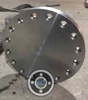
Different Types of Monel 400 Flanges
UNS N04400 Reducing Flanges

900 LBS Monel 2.4360 SWRF Flanges
Monel UNS N04400 Spectacle Blind Flange
300 LBS Monel Nipoflange Flanges
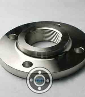
Nickel Alloy 400 Threaded Flange

Alloy 400 SORF Flanges
Monel UNS N04400 Lapped Joint Flange
600 LBS Monel 400 Slip On Flange
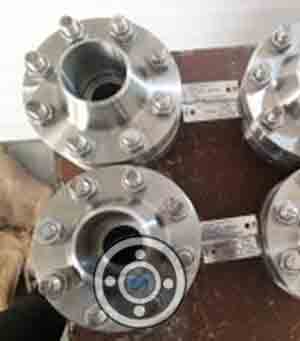
Monel Orifice Flanges
15 NB Astm B564 UNS N04400 Long Weld Neck Flange

Alloy 400 Girth Flanges
1500 LBS Monel 400 Blind Flange
ASTM B564 UNS N04400 Screwed Flange
150 LBS Monel Alloy 400 WNRF Flange
Monel Alloy Socket Weld Flange
Nickel Alloy 400 Expander Flanges
2500 LBS Monel Alloy BLRF Flanges
Monel 400 Weld Neck Flanges
5000 NB Monel 2.4360 Tongue & Groove Flange
Din 2.4360 Ring Joint Flange
Monel 400 Pipe Flanges
Monel Flanges
Monel Blind Flange
Monel Alloy Flanges

Alloy 400 Flanges
ASTM B564 UNS N04400 Flanges
Nickel 400 Flanges
Dimensional Tolerance of ASTM B564 UNS N04400 Flanges
| Flange | Tolerance Table | |
|---|---|---|
| D | Inside Diameter (I.D.) |
|
| K | Length of hub |
|
| B | Diameter of contact face |
|
| A | O.D. (Outside Diameter) |
|
| J | Diameter of hub at base |
|
| P | Drilling |
|
| Eccentricity of bolt circle with respect to facing |
|
|
| H | Diameter of hub at point of welding |
|
| C | Thickness |
|
What are the characteristics of Monel 400 Slip on Flanges?
- High-temperature resistance to seawater and steam
- Excellent resistance to brackish or seawater flowing at high speeds.
- In most freshwaters, it has excellent resistance to stress corrosion cracking.
- When de-aerated, they are particularly resistant to hydrochloric and hydrofluoric acids.
- Resistance to neutral and alkaline salts is exceptional.
- Resistance to stress corrosion cracking caused by chloride
Monel 400 Pipe Flanges Fabrication
Monel 400 Flanges is easily welded with appropriate filler metals utilising gas-tungsten arc, gas metal arc, or shielded metal arc methods. There is no requirement for post-weld heat treatment; however, thorough cleaning after welding is essential for best corrosion resistance; otherwise, contamination and embrittlement are risks.
Nickel Alloy 400 Flange Density & Melting point
| Density | 8.83 g/cm³ |
| Melting point | 1300-1390 ℃ |
In what applications is ASTM B564 Alloy 400 Flanges used?
- Fossil Fuel Power Plants
- Oil And Gas Industry
- Marine Applications
- Nuclear Power
- Ship Building
- Power Plants
- Paper & Pulp
- Refineries
Flanges Material
Pipe Fittings Material
Other Products